Scan75 Control Program User Manual
A program to control the Uniden Bearcat UBC75XLT, BC75XLT and SR30C
Scanners
© Nick Bailey 2019-2023
http://www.nick-bailey.co.uk/scan75
You are requested to fully read this and any other documentation prior to
installing and using the Program.
In using the Program you are agreeing to accept all of the
terms and conditions stated herein.
Manual Version 1.3.0.0 - 24 December 2023
Contents Index
Author and Copyright Information
This program has been written by Nick Bailey and is his sole Copyright.
Scan75 Control Program © Nick Bailey 2019-2023
 Please
Donate to my supported charity which I would very much appreciate, as
will they, and will keep me developing and supporting the programs.
Please
Donate to my supported charity which I would very much appreciate, as
will they, and will keep me developing and supporting the programs.
The Program is currently Freeware (see http://en.wikipedia.org/wiki/Freeware)
with a Careware/Charity status and objective (see http://en.wikipedia.org/wiki/Careware).
It
operates with no limitations. The author reserves the right to change
the program status and limitations on any future release. Existing
releases will retain their status and your right to use them but support may
not be available.
This document may mention Scan75, Scan75 Program or Scan75 Control Program.
They are the one and the same and are to be read, understood and respected
as being so and thus covered by the Copyright, Warranty, Liability and
License Agreements detailed here and in Section/Chapter 7.0
of this document.
The creator of this program asserts that the appearance of the user
interface screens is a work art and therefore attracts Copyright protection
under UK and EU law.
This product contains Uniden proprietary and/or copyright control
codes. Used with permission.
My website can be found at http://www.nick-bailey.co.uk
and for this program at http://www.nick-bailey.co.uk/scan75
My contact Email address is:
| scan75 |
@ |
nick-bailey |
. |
co |
. |
uk |
Preface
Welcome to the Scan75 Control Program specifically designed for controlling
the Uniden Bearcat UBC75XLT, BC75AT, SR30C and Albrecht AE75H scanners.
The UBC75XLT is a European market orientated scanner
The BC75XLT is an American market orientated scanner
The SR30C is an American market orientated scanner
The AE75H is a European market orientated scanner based on an
Albrecht licensed clone of the UBC75XTL scanner
These scanners are supported by some commercial programs but these are
either expensive or lack real time control functions and only support data
loading and editing. Scan75 supports both data management and real
time control of these scanners.
All the above reasons are why I have written the Scan75 Control Program.
This program supports both the UBC75XLT, BC75XLT, SR30C and AE75H
scanners. However I must point out that as I do not have the BC75XLT,
SR30C and AE75H scanners to test against there may be some issues I may have
to resolve. I will only know of these issues if people are kind enough
to let me know what they are.
I would also like to take this opportunity to say a BIG thank you to
Chris Taylor and Moonraker (UK) Limited who sent me a UBC75XLT scanner
so I can support you folk AND hopefully generate some new charitable
donations to the DEBRA charity. As you know my software is free and fully
supported (even at weekends) and many kind people have made donations to
DEBRA.
PLEASE NOTE! It may be illegal to listen to or
record certain types of, or even *any*, radio transmission/traffic in your
particular Country, State or Jurisdiction. It is your
responsibility to check the legality of listening to or recording
any transmission. This program should ONLY be used in compliance
with the laws of your particular Country, State or Jurisdiction.
Please read this manual in conjunction with your scanner's Owner's User
Manual.
Donate To DEBRA Charity
The Program is currently Freeware (see http://en.wikipedia.org/wiki/Freeware)
with a Careware/Charity status and objective (see http://en.wikipedia.org/wiki/Careware).
It
operates with no limitations. The author reserves the right to change
the program status and limitations on any future release. Existing
releases will retain their status and your right to use them but support may
not be available.
Please Donate to DEBRA my supported charity which I
would very much appreciate, as will they, and will keep me developing and
supporting the programs.
Send Me Your Comments
After you have had the opportunity to use Scan75 for a while it would be
appreciated if you could send me your comments, good or bad. You can
do this via the "Comments" item on the menu bar or by visiting the Scan75
website page.
Program Overview
The program is a standalone portable application that only requires
Microsoft Windows and the Microsoft .NET V4.5 platform to be
installed. The program is designed to fully function with a scanner
attached. Without and attached scanner then functionality is limited.
The User Interface design has been created to give maximum and easy control
from a single Main Control Panel form. There are also three
other important user interface forms that cater for the Viewing and Editing
of Scan Channels, Search Frequencies, and Global
Lockout Frequencies. Use of other forms/panels has been
limited to confirmation dialogs, error messages, options, file management
and other items not frequently used.
HELP - All control groups, keys, buttons and displays have "Mouse
Over" help prompts. The Menu Help function will display the Scan75-Manual.html
in your default Web Browser.
Controls are grouped together into the following main logical function
groups (some of which contain sub groups):
- Scanner General Controls
- Band Plan Settings
- Priority Mode Settings
- Search/Close Call Settings
- Global Frequency Lockouts
- Close Call Settings
- Scan/Search/Service Banks Settings
- COM Port Settings
- Scanner Display and Scan Control Buttons
- Notepad and Autosave
- Audio Recorder and Player
These are supported by information displays:
- Virtual Scanner Display
- Signal Strength Meter
- Program/PC Clock Display
- COM Port Display
- Program Latency
Finally there is the Menu Bar. Here besides the typical About
and Help menu items you will find the following additional scanner
functions:
- Save Scanner Settings
- Load Scanner Settings
- Reset Colour Scheme
- Butel .RSF File Load and Save
- Options
The Global Frequency Lockouts, Scan Banks and Search
Banks are supported in View/Edit mode with their own dedicated
data entry forms which contain additional functions like Save To File,
Print, Add, Delete, Copy, Move and Find.
NOTE! The UBC75XLT, BC75AT, SR30C and AE75H scanners have some
differences which affect the program's main panel content depending on which
scanner is connected. This manual will for the most part will use
images for the UBC75XLT scanner when describing program controls and
functions. I will however mention differences in the text where
appropriate.
The following two sections clearly show the main panel visual differences
and a corresponding table of differences. With these in mind one
should have no difficulty in understanding the differences and relevance of
documentation.
Program Main Panel for UBC75XLT and AE75H Scanners
The Scanner is in Scan Mode and Hold status. (Note: Model: UBC75XLT number
will change to AE75H as appropriate)

Program Main Panel for BC75XLT and SR30C Scanners
The Scanner is in Scan Mode and Hold status. (Note: Model: BC75XLT number
will change to SR30C as appropriate)

UBC75XLT - BC75XLT - AE75H - SR30C Differences
| Item / Function |
UBC75XLT and AE75H |
BC75XLT and SR30C |
| Battery Capacity / Charge Period |
14 Hours - 2300mAh |
14 Hours - 2300mAh |
| Backlight |
High |
High - BC75XLT
Low and High - SR30C |
| Band Plan 0 |
n/a |
n/a |
| Band Plan 1 |
Plan 1 |
USA |
| Band Plan 2 |
Plan 2 |
Canada |
| Band Step Size and Modulation Adjustments |
25 fixed frequency bands from 25MHz to 960MHz, steps of 5, 6.25,
8.33, 10, 12.5, 20MHz, and AM, FM modulation |
n/a |
| Weather Priority Alert WX |
n/a |
Yes |
| Pager Screening |
n/a |
n/a |
| Close Call Bands |
6 Bands |
5 Bands |
| Close Call Band Names |
VHF Low, Civil Air, VHF Hi, UHF |
VHF Low, Civil Air, VHF Hi, UHF |
| Modulation Types |
AM, FM (narrow) |
AM, NFM |
| Frequency Range 1 |
25MHz - 88MHz |
25MHz - 54MHz |
| Frequency Range 2 |
108MHz - 174MHz |
108MHz - 174MHz |
| Frequency Range 3 |
n/a |
n/a |
| Frequency Range 4 |
400MHz - 512MHz |
406MHz - 512MHz |
| Number Scan Channels |
300 (10 banks of 30 channels) |
300 (10 banks of 30 channels) - BC75XLT
500 (10 banks of 50 channels) - SR30C |
| Service Banks |
7 |
10 |
| Service Banks Names |
Emergency, Freenet, PMR, Marine, Civil Air, CB Radio, HAM Radio |
Weather, Police, Fire/Emergency, Marine, Racing, Civil Air, HAM
Ham Radio, Railroad, CB Radio, Other/FRS/GMRS/MURS |
Program Locale/Region Setting
This program is designed to run in en-GB locale mode where we use
the Full Stop/Dot/Period ( "." - ASCII decimal 46) as the decimal
mark/separator character and not the Comma ("," - ASCII decimal 44).
You DO NOT need to change your system's Region and Language settings
to use this program. You will however have to use the Full
Stop/Dot/Period ( "." - ASCII decimal 46) as the decimal
mark/separator character when entering data.
Program and Driver Installation
The program is written as a portable application requiring no installation
program. As long as you have Windows and the .NET V4.5
framework installed then getting the program up and running is simple
Obtaining and Delivery
The program and drivers can be obtained from my web site http://www.nick-bailey.co.uk/scan75. Here you
will find program information, download link and MD5 checksum information so
you can validate the integrity of your download.
The download will usually consist of a single ZIP file for the program and
separate driver .inf files.
Driver Installation
Windows 10 and 11 should already have a driver for your Scanner.
When connecting and powering on the scanner for the first time Windows 10
and 11 should detect the scanner and install the appropriate driver.
For other versions of Windows, or if your Windows 10 and 11 does not install
the appropriate driver, then please follow these instructions.
If you do not already have a USB driver installed for your scanner then you
will have to download and install the appropriate driver for your scanner.
This can be done by following the following steps:
- The download directory contains a file named CP210x_Universal_Windows_Driver.zip.
- Download the zip file to a directory of your choice on your PC and
extract both files. (NOTE! This should be a directory on the SAME
drive/partition that Windows is installed on, otherwise the driver
install may fail!!!!!)
- Connect your scanner to a USB port and then power the scanner
on. Windows will start to look/search for a driver. You can
cancel this search or wait for it to it to fail.
- If you wait for it to fail then you will be offered an option to
manually locate the driver.
- If you cancel you can then open Device Manager, navigate to the
Ports section where you will find an unknown device. Open
the properties for this device and on the Driver tab you can select to
install/update the driver.
- With 4) or 5) above you be be shown a dialogue box where you now need
to browse and select the directory where downloaded the .inf and
.cat files are located. Windows will now search for
and install the signed driver.
- Device Manager will now show/list Silicon Labs CP210x USB to UART
Bridge (COMn) in the Ports section.
NOTE! The Scan75 Control Program will try to locate a
powered on scanner on a USB/COM port does. If the scanner is not
powered on or the program fails to find the scanner then you will have to
identify and manually select the correct USB port yourself. See here.
Program Installation
To install the Scan75 Program is very straight forward. You will have
received Scan75 in either a ZIP file or as separate files. The program
has no specific install program and does not make registry changes.
Just follow these simple steps.
- Create a directory of your own choice on your PC. It is
suggested to give this directory a name like 'Scan75 Control Program'
for easy recognition
- Un-ZIP / copy ALL files and folders to the directory you have
just created. Scan75.exe will not run on it's own!
- Read the Scan75-ReadMe.txt and Scan-History.txt
files. They have important information
- It is suggested to create a short cut to the Scan75.exe file
on your desktop or elsewhere
- Optional/Suggested - backup the original distribution file(s) to a
safe location
- Read the Scan-Manual.html file to familiarise yourself with
the program
NOTE! It is suggested that you do not place the program in a
system directory like Program Files (x86) or Program Files
etc, as these directories require Administrator privileges and you
will encounter file write error issues unless you force the program to
Run As Administrator which is not recommended for security reasons.
Program Patch Installation
There may be times when just a Patch Release EXE file on its own is
released. This EXE file must be installed into the program
directory of a current Scan75 program installation. The EXE file will
not work on its own. If you are a new Scan75 user then you must first
install the base full release and then apply the patch.
Removal
The Scan75 Program can be simply and fully removed at any time.
CAUTION! The following steps will completely remove Scan75
Program and all your associated data. If you want to keep any
data files you have created then you should move/copy these files to another
directory first.
- Delete the folder you created and all the files
therein
- Delete the short cut you created (if any)
Upgrade Process
Upgrading to a later version of Scan75 is simple and straight forward.
Upgrading will retain your important configuration files. Following
all the steps of this procedure will also give you a backup version(s) of
the program to revert to should you wish or need to.
Warning! The program will either create or use any existing
configuration files it needs. These files are:
- scan75-ini.ini
- scan75-runlog.txt
Other files that contain your personal saved data / settings not be
overwritten by the installation process as they are not shipped with the
Scan75 Control Program. You are however strongly advised to back these
files up for your own protection, together with any of your own user files
you have created.
To upgrade follow these simple steps:
- Locate your current installation folder
- Create a new sub folder named Vn.n.n.n corresponding to the version
number of your currently installed version, e.g. V1.0.0.9
- Copy ALL the contents of the current installation folder into the new
backup Vn.n.n.n sub folder you just created
- Un-ZIP / copy the new program release files to the current
installation folder and OVERWRITE/REPLACE the existing files
- Read the Scan75-ReadMe.txt and Scan75-History.txt
files. They contain important information
- Read the Scan75-Manual.html for help or details on any new
functions that may have been added
If there are any release specific files or instructions then you will be
notified of these on the web site prior to downloading the program.
Running / Program Start-up
Running the program is a simple matter of invoking the scan75.exe
file. This can be done by mouse double clicking the scan75.exe
file or via a Windows shortcut link or by using the Windows 'run' command.
Running when Connected to a Powered On Scanner
When the program is started and a powered on scanner is present and
connected to the program's currently configured COM port then the program
will read ALL the scanner's current settings and data
values. This data will be used by the program as a "statement of
fact" regarding the scanner's data and model version.
Once running then any changes you make via the program will be
sent/committed to the scanner. Any changes you make directly on the
scanner will not automatically be sent to the Scan75 Control
Program. In simple terms the Scan75 Control Program is the dog
(master) and the scanner is the tail (slave).
It is important to understand this Master/Slave (Dog/Tail) operational
relationship so that you do not inadvertently lose data.
Where you do make changes on the scanner then you can use the Scanner
General Controls/Read button to force the program to completely
re-read the scanner. If you do this then for the duration of the read
process the scanner is the master and the program is the slave. This
means that if you have made any changes with the program that you have not
saved then they will be overwritten by the Read process.
Running with No Scanner Connected
When the program is started with no scanner attached, or powered on, or with
incorrect manual COM port selection then the program will enter No
Scanner Connected mode of operation. You will have to power on
your scanner and select the correct COM port manually or close and restart
the program. When a connection is made then the program will read the
scanners data as defined in the above "Connected" state. See here
for information about No Scanner Connected operation.
Controls and Functions
As already mentioned the Main Control Panel contains all the
essential controls and functions in one easy to understand and navigate
layout. Controls and Functions are grouped in containing titled and
outlined defined areas.
Some controls and functions are disruptive in that the scanner is
put into and taken out of Program Mode and doing this will disrupt/stop and
reset any Scan, Custom Search or Services Search that is in progress.
Also the scanner will automatically clear it's Close Call Hit Registers.
The non disruptive controls and functions are:
- Volume - including On/Off
- Squelch - including On/Off
- Lockout (L/O)
- Temporary Lockout (TL/O)
- Modulation (AM/FM)
- Scan Control (all)
- Notepad and Autosave
- Audio Recorder and Player
All other controls and functions are disruptive with the aforementioned
effect.
Title Bar

The program title bar displays the following information:
- Program Name
- Program Author
- Program Copyright
- Program Version Number - e.g. V1.0.0.1
- Program Website URL
- Scanner Model Number
- Scanner Firmware Version
- "No Scanner Connected" Message
The No Scanner Connected message will replace the scanner Model and Firmware
information.
Menu Bar
The menu bar is similar to any Windows menu bar. Here you will find:
DONATE
This will allow you to make a donation to the DEBRA
charity. Please do this in appreciation of this free program and my
user support.
Comments
This will allow you to anonymously give any comments you may have about
Scan75.
About
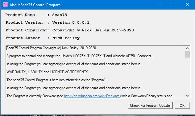
About provides the following:
- Program Name, Version, Copyright and Author information
- Warranty, Liability and License Terms and Conditions and other
information.
- Check for Program Update button (manual)
About will display program Name, Version, Copyright and Author information
together with Warranty, Liability and License Terms and Conditions and other
information.
Check for Program Update
If you press this button then the program will check your version against
the latest official full version on the Scan75 website. The response
will look as follows:
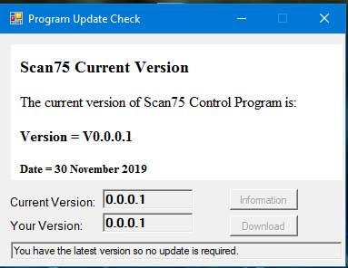
Depending on the version you have you will see one of the following
messages:
- "You have the latest version so no update is required."
- "Your version is NOT up to date. V1.n.n.n is now AVAILABLE!"
- "Your version is later than the official version. No update
available."
The above image shows that we have a version later then the official
version. If you see/have this condition then it means that you are
running a "special" patch or test version of the program.
Instead of using this manual check you my wish to enable the Automatic
Program Update Check on the Options menu.
Please Note! For both the manual and automatic program update
checks no data (other than the update information) is download or installed
to your PC. If you want the updated version of the program then you
must go and fetch it yourself.
Help
This will open the Scan75 User Manual file Scan75-Manual.html in
your default Web Browser. Besides this help file you will also find
that all control groups, keys, buttons and displays have "Mouse Over" help
prompts.
Support
This will open the Contact Us web page where you will find the support
Email address for Scan75.
Save Scanner Settings
This will save all the program's current scanner settings, channel
data, etc. to a file of your choice. This is in effect a complete
backup/snapshot of all data, all selected states and settings.
When this file is subsequently loaded then the program will send all the
data, states and settings to the scanner.
This save is FULL save and the file is marked with "#full#"
in the header. When the saved file is reloaded it will clear and
overwrite all the scanner settings.
It it suggested you choose a sensible and informative file name when saving
any data so that you can easily identify what the files contain when you
load them in the future.
Load Scanner Settings
This will load the settings and data in the chosen file into the program and
into the scanner. The file to be loaded may contain a full
backup/snapshot as made with the Save Scanner Settings menu item or
may just contain data you have previously selected and used the Save To
File function in any of the View/Edit forms.
If the file to be loaded is a FULL save file as marked with "#full#"
in the header, then when the file is reloaded it will clear and overwrite
all the scanner settings.
If the file to be loaded is a PART save file as marked with "#part#"
in the header, then when the file is reloaded it will only update those
scanner settings as defined in the file.
When you load a data file, if enabled, the Autobackup PREVnnnn
function (control via the Options Panel) will first save a copy of
the program's current scanners data settings to a PREVnnnn file for safety
just in case you have any unsaved work.
Reset Colour Scheme
This will reset the programs background colours to their default values.
The program allows the user to change the background colours used for the
Main Panel/Form, Menu Bar, and all Control Groups. In all there are
over 20 definable background areas that can be configured on the main
control panel form.
To configure an area colour then use a right mouse button click when
over the area and then select your chosen colour from the palette table.
Butel .RSF (Butel RSF File Save & load)
This menu has two drop down items.
- Save As Butel .RSF File
- Load .RSF File
The program supports the loading and saving of some specific
data as would be found in Butel's ARC75 program's user data
files. These load and save functions are specifically provided to
allow program interoperability and user data sharing between Scan75
and the Butel ARC75 program.
The loading and saving of Butel data files are PART and not FULL
datasets so when loaded no scanner data is cleared and the file content will
just update the current scanner settings.
The specific data field settings supported are:
- [NUMBANKS] - number of scan banks - (save only)
- [NUMCHAN] - number of scan channels - (save only)
- [C-BANK] - scan bank tag names - multiple, one for each bank - (load
and save)
- [C-CHAN] - scan channel settings (frequency, tag name, modulation,
delay, lockout, priority) - multiple, one for each channel - (load and
save)
- [SRLIMIT] - custom search settings (start frequency, end frequency) -
multiple, one for each custom search bank - (load and save)
All of the other scanner and user settings supported by Scan75 are not
compatible with Butel's ARC75 program support.
If you Load a Butel data file then the Butel file data will
overwrite any existing scanner data, as defined by the [C-BANK], [C-CHAN]
and [SRLIMIT] values. [NUMBANKS] and [NUMCHAN] data is ignored.
If you Save a Butel data file then all the above defined
fields/records are written.
Options
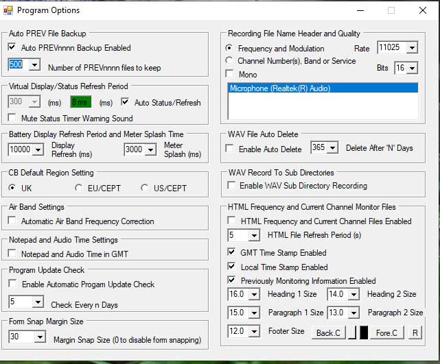
The Options Panel allows you to control the following settings:
- Auto PREV File Backup
- Virtual Display/Status Refresh Period
- Battery Display Refresh Period and Meter Splash Time
- CB Default Region Setting
- Air Band Settings
- Notepad Settings
- Program Update Check
- Form Snap Margin Size
- Recording Source File Name Header and Quality
- WAV File Auto Delete
- WAV Record To Sub Directories
- HTML Frequency Monitor File
Auto PREV File Backup
This function can be turned On or Off by checking or un-checking the check
box.
When enabled then every time you load a Scan75 scanner settings file or a
Butel .RTS file the program will automatically save the program's scanner
data settings to a PREVnnnn.txt file in the 'prev' directory of your
normal file load and save location.
The combo drop down box allows you to set the number of PREVnnnn files you
wish to keep. The default setting for this is 50 files but you can set
from 5 to 1000 files should you so wish. If you set say 100 then at
PREV0100.txt the file numbering will wrap back to PREV0001.txt and overwrite
existing files.
Virtual Display/Status Refresh Period
The program dynamically determines the best Display/Status Refresh periods
when the AUTO check box is checked. The default settings is AUTO.
You should always use the AUTO Status/Refresh unless you experience
specific communications and stability issues. If you are running natively
on a Windows machine then there should be no reason to manually select the refresh
period. Manual selection *may* be required if you are running the
program on a MAC or Linux PC.
Should manual configuration be required then the following information will
be of interest.
The display on the Main Control Panel and on the right here, show in
milliseconds the actual average time (latency) in any given 1
second period the program takes to do the following:
- Get all required status data from scanner
- Analyse said data
- Build and display the virtual scanner display.
A warning sound may be issued and the background colour changes as follows:
- If Status Poll Time is set to less than the actual average time
then colour goes RED and a system exclamation sound is issued.
- If Status Poll Time is set to greater than the actual average time
then colour goes ORANGE.
- If Status Poll Time is set to TWICE the actual average time
then colour goes GREEN.
For manual settings the you should set the Status Poll Times for GREEN
for reliability and command responsiveness. For more modern PCs /
laptops then a pole time setting of 20ms to 50ms should be achievable.
You can change the Status Poll Time refresh period from 5ms to
2000ms. It should be set to the lowest / fastest time possible
but not so fast that it is more often than not in the RED zone. It
defaults to the normal/default and conservative value of 300ms. For
most people and systems a faster/lower value should be
selected.
When running on a non native Windows PC, e.g. Apple MAC machine, Virtual
Machine software or Windows Emulator software, then the Status Poll Time
may have to be significantly increased to avoid warnings or errors.
The Mute Status Timer Warning Sound check box when checked will turn
off the audio warning system exclamation sound. It is
inevitable that periodically your PC's system performance will be impacted
by other events and programs and these could temporarily put Scan75 status
times into the Red/Warning zone due to a slower average time. The more
aggressively faster you set the status poll times the more frequently
warnings could occur.
Running with ORANGE is normally OK but not advised. Depending on
how deep into the orange you go you may get USB/program response issues.
Running in the RED will cause user interface command issues as the program
is spending all it's time attending to status and display duties. You
will almost certainly experience some USB/program response issues.
Battery Display Refresh Time
The battery voltage default update period is every 10 seconds. This
time period can be adjusted 5 seconds and 60 seconds.
Battery Display Splash Time
On program start-up if a scanner is attached and powered on the Battery
Meter will be displayed and will auto close after a default 3 second
'splash' period. You can change this default time from 0 second to 5
seconds. If a value of 0 is set then no 'splash' will occur on
program start-up.
CB Default Region Setting
Here you can set your default CB region to be used when using the Frequency
Prefix Key of "cb". Setting a default
region will enable you to use a prefix key of just cb as opposed to
cbuk, cbeu or cbus.
Air Band Settings
Here you can set that Civil Air Band ATC frequencies will be automatically
corrected to the correct real frequency without have to enter the Frequency
Prefix Key of "ab". Any frequency entered
from 108MHz to 137MHz will automatically be corrected to recognised ATC
Channel Frequencies thus overriding the Uniden scanner's default 8.33KHz
step values.
This function is also applicable to the Direct Frequency
Tuning feature/control.
Notepad Settings
The Notepad and Autosave functions can log the time in GMT or Local
time. For GMT check the Notepad Time in GMT check box. The
chosen setting will also be indicated in the Program/PC Clock display by the
chosen time setting having a light green coloured background.
Program Update Check
The program can automatically check for updates. It *always*
defaults to never check. If you leave at the default setting
then please remember to occasionally do a manual program update check via
the About menu and the Check For
Program Update function.
To enable the program to automatically check for updates then check the Enable
Automatic Program Update Check check box. The default interval
period in days between update checks is 5 days. However you can use
the Check Every n Days combobox control to select 1, 2, 3, 4, 5, 6,
7, 8, 9, 10, 20 or 30 day intervals.
The automatic update check will only make a single check per day regardless
of how many times the program is started and stopped.
Should a later/updated version of the program be available then you will be
informed accordingly. Please Note! For both the manual
and automatic program update checks no data (other than the update
information) is download or installed to your PC. If you want the
updated version of the program then you must go and fetch it yourself.
Form Margin Snap Size
Most of the program's main windows/forms can "Snap To" either of the
four screen corners or to the screen's top, bottom or sides. The
margin size to which a window/form has to be dragged to, or within, can be
set from 0 to 150 pixels. If a value of 0 is set then the Snap To
feature is disabled. For any other non zero value then when a major
window/form is moved to/within the margin snap size then the window/form
will snap to the corresponding corner or edge location.
Recording Input, File Name Header and Quality
Here you can choose the recording input source, how the recorded audio files
are named and the quality of the recording. Time is in GMT/UTC or
Local as determined by the option setting Program Time Settings in
GMT/UTC checkbox.
All available sound inputs available for recording from are listed in the
selection box. By default when the program starts the current default
input as set in Windows is selected and highlighted in blue. Should
you wish to change the input source then select one of the other listed
input items. If you want this to be your default input then you should
change your default input source in Windows.
If Frequency and Modulation is selected then the file names will be of
the form "frequency-modulation-yymmdd-hhmmss-timezone.wav".
For example 01202250-AM-141108-104737-LCL.wav is a recording of
frequency 120.2250 MHz in AM modulation, on year 2014, month 11, day 08,
started at time 10 hours, 47 minutes and 37 seconds Local Time.
Example:
01180083-AM-200310-185556-LCL.wav
If Channel Number(s), Band or Service is selected then the file names will
be of the form "name-yymmdd-hhmmss-timezone.wav". In this
form then name will be either the Scan Banks Channel Number(s), or the
Search Bank Name or the Services Bank Name depending on the type of scan
being done.
Examples:
- Chans_024_054_01250000-AM-210421-172402-LCL.wav for a Scan Bank
Channel scan
- Search_Bank_1_00271300-FM-210421-172437-LCL.wav for a Search
Bank scan
- Services_Emergency_00866550-FM-210421-172638-LCL.wav for a
Services Bank scan
The Sample Mono if checked will record just 1 audio
channel. If not checked then the recording will be in Stereo
- 2 channels.
The Sample Rate changes the quality of the recorded WAV
file. Sample rates of 08000, 11025, 16000, 22050, 32000 and 44100
are supported. For basic voice transmissions then the default rate
of 11025 is more than adequate and is the default rate. For medium
quality music recording then 22050 can be chosen. For CD/HiFi
quality then 44100 should be chosen. Please note that WAV files even
at a sample rate of 11025 are large in size and going from 11025 to 44100
will quadruple the size of the WAV file.
The Sample Bits changes the bit depth and quality of the recorded
WAV file. Sample bits of 8, 16 and 32 bit floating point are
supported. For basic voice audio 8 bits is adequate but the default
is set to 16. As mentioned the sample Rate, Bits and Mono affects the size
of the record WAV file so it is recommended that you select the rate and
bit depth to values that give you acceptable audio recording for the
best/minimum recorded file size.
The option selections are disabled if the program is currently recording.
WAV File Auto Delete
Depending on your usage of the audio recording function you may find old WAV
files building up and taking valuable storage space.
WAV file management and moving/backup is a User responsibility.
To aid WAV file management you can choose to enable the WAV File
Auto Delete function, to permanently delete WAV files that
are older than the selected number of days. When enabling
this function you will get a warning message when the program closes which
you should review and check the selected days, after which deletion will
occur, is correct.
The default settings are: Off/Disabled and 365
days.
If you have enabled WAV Record to Sub Directories
then Scan75 will prompt for each directory with WAV files older than the
specified number of days. You can cancel out of each or all
remaining directory checks.
WAV Record To Sub Directories
If this option is checked then the recorded WAV audio files will be
placed in different sub directories of the .\wav folder. The
target sub directory is determined by the type of scan the scanner is
doing:
- If doing Scan Banks Channel scan then the target directory is .\wav\scan
- If doing a Search/Custom scan then the target directory is .\wav\srch
- If dong a Services scan then the target directory is .\wav\srvs
- For all else the .\wav directory may be used
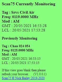
HTML Frequency and Current Monitor Files
Scan75 can create an HTML Frequency Monitor File a Current Channel Monitor
File. These files are called ScannerFTP.html
and Current Channel.txt respectively and reside in
Scan75's program directory.
This HTML file contains information regarding the Current Frequency being
monitored and optionally the previously monitored frequency information.
The option here are:
- HTML
Frequency and Current Channel Files Enabled Checkbox:
Enables/Disables the creation and updating of the HTML file.
- HTML File Refresh Period: Sets the HTML <meta
http-equiv="refresh" content="1"> tag in the HTML file which tells
Web Browsers how often to refresh/reload the file. The available times
are 1 to 10, 20, 30, 40, 50 and 60 seconds.
- GMT Time Stamp Enabled Checkbox: Enables/Disables the GMT Time
Stamp entry in the generated HTML file.
- LCL Time Stamp Enabled Checkbox: Enables/Disables the Local
Time Stamp entry in the generated HTML file.
- Previously Monitoring Information Enabled Checkbox:
Enables/Disables the Previously Monitoring Information in the generated
HTML file.
- Heading 1 Size: Sets the size (in px units) of the
"Scan75 Currently Monitoring" heading.
- Paragraph 1 Size: Sets the size (in px units) of the
Currently Monitoring Tag: Freq: Mod: GMT: and LCL information.
- Heading 2 Size: Sets the size (in px units) of the
"Previously Monitoring" heading.
- Paragraph 1 Size: Sets the size (in px units) of the
Previously Monitoring Tag: Freq: Mod: GMT: and LCL information.
- Footer Size: Sets the size (in px units) of the file
footer information.
- Background Colour (Back.C): Displays Colour picker/setter
dialogue for selecting a background colour for the HTML file.
- Foreground Colour (Fore.C): Displays Colour picker/setter
dialogue for selecting a foreground/text colour for the HTML file.
When setting the HTML Refresh period to small / quick time periods (e.g.
1 second) then if you are also frequently sending this file to a remote
web server/site then there is the possibility that the viewer's browser
will attempt to refresh/reload the HTML file whilst it is being updated on
the web server/site. When this happens then the browser view of the
file will become permanently blank until the user manually refreshes their
browser's view (hence the "If this view goes blank then refresh your
browser").
The Current Channel Monitor file contains the necessary
information for RRUK's Scanner Linker Program (rruklinker.exe) to lookup
in their database relevant information for the frequency your scanner is
currently listening. The are no user configurable setting for this
file other than Enabled/Disabled.
Please see RRUK's program information on using the "Current Channel.txt"
file.
Note! RRUK is a subscription service and operate completely
independently.
Note! The Current Channel file is also for use by any other 3rd
Party software should they wish to.
Scanner General Controls Group

These are general scanner controls plus specific Power
Off/Reset/Read controls.
Volume
Adjust Volume level here using the slider bar. Set level is
also numerically indicated. This is a non disruptive control.
In addition to the slider there is a volume On/Off button. If
turning the volume to Off then the current volume level is saved and
will be restored when the volume is turned back On again. If
the volume is Off and the slider is adjusted to a non zero value
then the volume is set back to On.
Squelch
Adjust Squelch level here using the slider bar. Set level is
also numerically indicated. This is a non disruptive control.
In addition to the slider there is a squelch On/Off button. If
turning the squelch to Off then the current squelch level is saved
and will be restored when the squelch is turned back On again.
If the squelch is Off and the slider is adjusted to a non zero value
then the squelch is set back to On.
Backlight
This button turns the scanner's Backlight ON and OFF on the UBC75XLT,
BC75XLT and AE75H scanners.
On the SR30C scanner then it sets Backlight to LOW, HIGH and OFF.
Note! The scanner will automatically turn it's Backlight OFF after
15 seconds to preserve battery life.
This is non disruptive.
Battery Voltage
The current measured battery voltage is displayed just below the Battery
Charge display. The battery voltage is updated every 10
seconds. This time period is user adjustable between 5 seconds and 60
seconds via the Options Panel.
If you mouse hover over this display then the pop-up graphic Battery
Voltage Charge Meter (here) will be displayed for
the duration of the mouse hover event or the meter auto close timeout.
This is non disruptive.
Key Lock
The check box allows the setting of the Key Lock status.
Note! Setting the Key Lock will block some program
functions.
Power Off/Reset/Read Controls
Power Off Scanner
This will initiate a Power Off of the attached scanner. You
will get a confirmation dialogue to confirm the power off.
Reset Scanner
This will initiate a Factory Reset of the scanner. All user data will
be deleted and the factory defaults settings will be restored. Before
the reset is carried out you will be presented with a Reset confirmation
dialog. Only select OK if you wish to continue with the reset.
Note! As soon as the scanner reset has completed the program
will read all the scanner settings and data back. Please be sure you
have saved to file any settings and data you wish to retain as they will be
overwritten once the reset is complete.
Read Scanner
This will initiate and immediate Read of the attached scanner.
There are no confirmation dialogues.
The main uses of this Read function is to allow the program to pick
up any changes made directly on scanner itself and not via the
program. i.e. Re-synchronise the program to the scanner.
Band Plan Group

Here you can see which current Band Plan the scanner is set
to. It is not possible to change the Band Plan with this
control. To change Band Plans you must use the scanner's Power On and
Keyboard method.
Note! Available settings depend on the scanner attached. For
the UBC75XLT and AE75H this will be Plan1 or Plan2.
For the BC75XLT and SR30C this will be USA or Canada.
Priority Mode Group

Here you select the Priority Mode of the scanner. Off,
Scan, Scan Plus and Do Not Disturb being the
available settings.
Search and Close Call Group

Here you select the Search and Close Call response settings.
Delay has available settings of ON and OFF.
Direction controls the default search direction either Up or
Dwn(Down)
Global Frequency Lockouts Group

This control gives access to Viewing and Editing the scanner's stored Global
Frequency Locks.
When View/Edit is pressed then a new form is loaded.
View/Edit Global Frequency Lockouts

Here you can Add new frequencies to the Global Lockout list.
Entered frequencies are validated against the scanner's permitted frequency
ranges/limits.
You can also Select, via the check boxes, those existing frequencies
that you may wish to Delete or Save To File. The Select
All / Deselect All, Delete, and Save To File buttons
will be appropriately enabled and change their foreground colour to Green to
signify their availability.
This Save To File is a PART save file as marked with "#part#"
in the header and when the file is reloaded it will only update those
scanner settings as defined in the file.
The Print Form button will raise a printer dialogue where you can
select the required printer and printer properties to print the form.
Close Call Settings Group

Here you can control the Close Call Settings of the scanner.
Close Call Mode
Set close call mode. Available settings are: Off, Priority
and Do Not Disturb.
Close Call Bands
Set which bands will accept/respond to close call signals.
Available band settings are: VHF Low, AIR, VHF Hi,
and UHF.
Note! At least one band must be set. If not then VHF
Low will automatically be set.
Close Call Alert
Set if a scanner alerts on close call with Beep and/or display Light.
Scan / Search / Services Bank Settings Group
This large group contains the main Scan, Custom Search and Services
bank settings
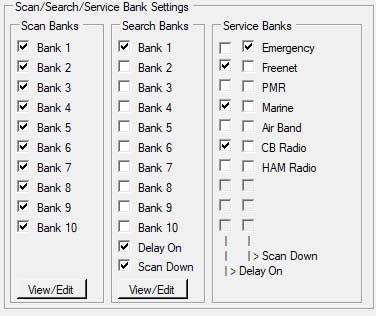
Each check box has a mouse over tool tip. For Scan Banks then this
will be Bank n or the Bank Name you have defined. For Search Banks
this will be the Bank n or the Bank Name you have defined and the
currently set frequency range. For Service Banks this will be the
Service name.
Scan Bank Settings Group
This gives access to Setting, Viewing and Editing the scanner's Scan
Banks and Channel settings.
Here each of the scanner's 10 channel banks can be enabled or disabled for
when the scanner is scanning in Scan Mode.
Note! Although the banks are named Bank 1 to Bank
10 if you have given a bank a Bank Tag Name in the View/Edit
panel then this will be shown (possibly truncated) on the main control panel
and when you mouse hover over that bank a pop-up will appear with the Bank
Tag Name you have actually allocated to the bank.
When View/Edit is pressed then a new form is loaded where you have
full control over channel data and settings.
View/Edit Scan Bank Settings
The following new form/panel will open when the View/Edit button is
selected.
Note! The BC75XLT and SR30C scanners do not
support modulation change so this column will not be visible with these
scanners.
Note! The SR30C scanner has 50 channels per bank
so one has to use the vertical scroll bar to see channels 31 to 50.

Unlike other programs that use a tabbed interface to each Banks data I have
chosen to consolidate all the channel data onto a single navigable form with
a scrollable grid view of the channel data.
The main advantage of doing this is that one can sort the data by column (by
clicking column header) and also select data in different banks.
The vertical height of the form/grid has been chosen so that channels are
paged up and down in 30 channel / 1 bank chunks at a time. One page up
and down per bank.
Grid Columns / Data Fields
The column/field details (left to right) are as below: (all columns/fields
can be sorted by clicking the field/column header)
The following columns/fields are always accessible:
- Row Header - this is a blank non editable field used to select
a row in the grid. It can be used for Quick Search/Fast Tune.
- Bank - this is a fixed named non editable field. It
can be used for Quick Search/Fast Tune.
- Bank Name Tag - this is an editable field allowing you to name
a bank. The program will automatically apply the name to all
channels/rows in the applicable bank. Note! This is
a program specific function only. The scanners do not support bank
naming. However any name you give a bank will be saved and loaded
by the program. Additionally the bank name will be shown on the
main control panel and appear as a pop-up when you mouse hover over that
bank on the main control panel form.
- Channel Number - this is a fixed named non editable
field. It can be used for Quick Search/Fast Tune.
- Frequency - this is an editable field allowing you to enter a
frequency. The format is nnnn.nnnn MHz. Any entered
frequency is check for an Out of Band value. Entered
values are sent to the scanner and the scanner may adjust the frequency
you enter to its nearest supported Band Plan step value.
If this happens then the program will change your entered frequency to
the value chosen by the scanner. It can be used for Quick
Search/Fast Tune. This input field also supports Air
Band Frequency Correction and CB Channel and Marine
Channel direct input via associated prefix keys. See Frequency
Prefix Keys.
- Select - this editable check box is used in conjunction with
the Channel Select and Select Function
buttons.
The following columns/fields are only/conditionally available if the Frequency
field contains a value other than 0000.0000.
- Modulation - (UBC75XLT and AE75H only) this is a
conditionally editable field via a combo box. Available values are
AUTO, AM, and FM. The default value is AUTO
which will be changed to AM, or FM by the scanner
depending on the current Band Plan setting. You can also
force/choose AM or FM should you wish to.
- Delay - this is a conditionally editable field via a combo
box. Available values are OFF and ON. A
double left-mouse-button will toggle the setting.
- Lockout - this is a conditionally editable field via a combo
box. Available values are LOCKED and UNLOCKED.
A double left-mouse-button will toggle the setting. This field
will always display LOCKED until a valid frequency is entered
and it will then automatically change to UNLOCKED. Any LOCKED
channels will be skipped during a Scan.
- Priority - this is a conditionally editable field via a combo
box. Available values are OFF and ON. A
double left-mouse-button will toggle the setting. Only one
priority channel is allowed per bank. If there is already one Priority
channel in a bank and you select another channel in that bank to be a Priority
channel then the program will flip the Priority of the
previously set channel.
Frequency Prefix Keys
The frequency input field supports several Frequency Prefix Keys.
These keys fall into the following categories:
- Frequency Modification Keys - civil airband frequency
correction
- Frequency Quick Input Keys - quick frequency input for known CB
and Marine Channels
Table below show examples of inputs and actions taken.
| Prefix Category |
Prefix(any case) |
Prefix Example |
Prefix Action Frequency |
Prefix Action Modulation |
Prefix Action Tag Name |
| Civil Airband Frequency Correction |
ab |
ab118.030 |
Set 118.0250MHz |
AM |
None |
| UK CB Channel Quick Input |
cbuk |
cbuk10 |
Set 27.69125MHz |
FM |
CB UK Chan 10 |
| EU/CEPT CB Channel Quick Input |
cbeu |
cbeu19 |
Set 27.18500MHz |
FM |
CB EU Chan 19 |
| US CB Channel Quick Input |
cbus |
cbus40 |
Set 27.40500MHz |
AM |
CB US Chan 40 |
| Default CB Region Options Setting |
cb |
cb12 |
Set 27.71125MHz (UK example) |
FM or AM |
CB UK Chan 12 |
| Marine Channel Band A Quick Input |
ma |
ma25 |
Set 157.2500MHz |
FM |
Marine Chan 25 A |
| Marine Channel Band B Quick Input |
mb |
mb25 |
Set 161.8500MHz |
FM |
Marine Chan 25 B |
| Marine Marina 1 Channel |
m1 |
m1 |
Set 157.8500MHz |
FM |
Marine Chan M1 |
| Marine Marina 2 Channel |
m2 |
m2 |
Set 161.4250MHz |
FM |
Marine Chan M2 |
The Civil Air Band Correction requires a little explanation with regards to
Channel Spacing. This well explained in this Wikipedia article. With the arrival of 8.33kHz
spacings between channels then the frequency (often called or refered to as
channel) Air Traffic Controllers will tell pilots to set on their radios
will not be the actual frequency that the radio uses. Looking at the
table below you will see that the Uniden scanner sets the correct actual
frequency in some cases but it also sets an incorrect frequency (shown in
bold and underlined) in other cases. In addition please note that the
lines maked with an * are not official frequencies/channels that Air Traffic
Controllers will call. When I enter these unoffical frequencies on my
certified transceiver then the radio automatically changed them to the
alternate values (column two) and the actual frequency used similary changes
(column three).
Offical 25.0 kHz channels / spacings end in: 00, 25, 50, 75
Offical 8.33 kHz channels / spacings end in: 05, 10, 15, 30, 35, 40, 55, 60,
65, 80, 85, 90
Not used 8.33 channels / spacings end in: 20, 45, 70, 95
ATC Controller    Radio Sets        Actual frequency   Uniden Scanner    Step/Spacing
Pilot Dials       Displays          used by radio      Sets              kHz
118.000	          118.000           118.0000           118.0000          25.0
118.005           118.005           118.0000           118.0000          8.33
118.010           118.010           118.0083           118.0083          8.33
118.015           118.015           118.0166           118.0166          8.33
118.020*          118.025           118.0250           118.0166          8.33
118.025           118.025           118.0250           118.0250          25.0
118.030           118.030           118.0250           118.0250          8.33
118.035           118.035           118.0333           118.0333          8.33
118.040           118.040           118.0416           118.0416          8.33
118.045*          118.040           118.0416           118.0416          8.33
118.050           118.050           118.0500           118.0500          25.0
118.055           118.055           118.0500           118.0500          8.33
118.060           118.060           118.0583           118.0583          8.33
118.065           118.065           118.0666           118.0666          8.33
118.070*          118.075           118.0750           118.0666          8.33
118.075           118.075           118.0750           118.0750          25.0
118.080           118.080           118.0750           118.0750          8.33
118.085           118.085           118.0833           118.0833          8.33
118.090           118.090           118.0916           118.0916          8.33
118.095*          118.090           118.0916           118.0916          8.33
118.100           118.100           118.0100           118.1000          25.0
The above Uniden scanner frequency setting discrepancy for Civil Air Band
actual frequencies continues throughout the 108MHz to 137MHz frequency
range. By using the "ab" prefix, or using the Automatic Air Band
Frequency Correction setting in the Options menu then the
Scan75 Control Program will override the scanner and set the correct actual
frequency required.
NOTE! In reality the UBC75XLT and BC75XLT set the correct
8.33kHz frequency for all but the two unofficial .020 and .070 values.
For the other two unoffical .045 and .095 values it sets the correct
frequency. In terms of end user usage then the Airband Correction
feature is only required to cover currently unofficial ATC usage. For
those that also have/use the Uniden 125 series of scanners then you will see
that the 75 scanners are significantly better at handing the 8.33kHz
spacings. Scan75 was developed from the Scan125 code base and as I
have users who have both models of scanners I have chosen to leave the Air
Band correction function in Scan75.
Bank View Group Controls
Across the top of the form, from the left, are the Bank View Controls
- Bank 1 to Bank 10. These give fast access to the
start of each bank. e.g. pressing Bank 3 button will scroll
the start of Bank 3, (3 - 01 and Channel 061), to the top of the viewable
grid.
Fast Tune and Hold Group Control
Pressing the Tune button will cause the scanner to directly
tune/jump to the chosen channel.
One can also perform a Fast Tune by double left mouse button
clicking any of the cells in the Header, Bank, Bank Name
Tag, Channel No. or Frequency fields.
Find Group Control
Pressing the Find button will open a Find Form dialogue box
where you can enter either a simple string search term and/or a
frequency. This is a simple search looking for the frequency you have
entered. There are no advanced "this and than but not the other"
options. The Find command is currently restricted to finding
data in the Frequency fields only. However all table
columns are sortable by clicking the header field so like data is also
readily grouped together, e.g. all modulations of the same value.
When entering a frequency into the Frequency box the entered
frequency is formatted to MHz format. So "125" is changed to
"0125.000", "125.6" is changed to "0125.6000". Only the digits
0,1,2,3,4,5,6,7,8,9 and a decimal point are accepted.
When the required data is found the table view focus is taken to that table
cell and the cell background colour is set to light blue to highlight the
found data. This will happen for all subsequent finds. All found
cells in this find/search session will remain back highlighted until the Find
Form is closed. This means that you can change find/search data
within a session and build up a back highlighted composite view.
All highlights are removed on form closure.
The Find button will find and highlight data cell by cell on each
button click. The Find All button will traverse the whole
table highlighting all found data.
Channel Select Group Controls
These Select All, Select B1 ......... Select B10
buttons allow the selection of all channels in all banks, all channels in
one bank, or any combination of banks. When one of the buttons has
been selected the button colour will turn to Green and it's label change to
Deselect.
The Select Count Display displays the number of currently selected
channels.
Selecting one or more channels will enable the Select Function Control
Group buttons.
Function Select Group Controls
There are six function command buttons in this group. These commands
will ONLY operate on the selected channels. When a command
button is available for use the button colour will turn to Green.
- Delete - this will delete all data associated with the selected
channel(s)
- Save to File - this will save all data associated with the
selected channel(s) to a file of your choice. A File Save dialogue
will be shown. This save is a PART save and the file is
marked with a "#part#" and when the saved file is reloaded it
will only overwrite the scanner settings as defined in the file.
- Format CSV - when checked the Save To File function
will create a CSV file containing Frequency in MHz and Modulation
only. No file headers are added. If you wish to share your
data with others in CSV format then check this option before
pressing. To use / import a CSV file then you have to use the Scan75Convert
utility program.
- Copy / Move - this will copy all the data associated with the
selected channels into a copy buffer. This will then enable to Paste
and Move buttons. The Copy / Move button will then
turn Yellow to indicate that a Copy / Move action is in
progress.
- Paste - this will Paste the data in the copy buffer to
the selected target location. To select a target location
simply mouse left button click the header field to select and highlight
the whole row. The data copied will now be pasted to here
when you select the Paste button.
- Move - this will Move the data in the copy buffer to
the selected target location. To select a target location simply
mouse left button click the header field to select and highlight the
whole row. The data copied will now be moved to here when
you select the Move button. The source data will be
deleted only after the move has been successful.
Store Group Control
The Store button will ONLY operate if the Main Control
Panel, Scanner, Store button has been pressed or the Close Call Bank
register Store button has been pressed. If a frequency has
been asked to be stored then this button colour will turn Green to signify
that a store is pending. The button will not be enabled until an unused
channel store location has been chosen. To choose a channel store
location one has to left mouse button click the channel row header field
on the far left of the row. The whole row colour will now turn Blue to
indicate that the channel row has been successfully selected.
If the desired location already contains data then an error message dialogue
will be shown asking you to select another location/channel to store the
data to.
Any pending store is cancelled on form closure.
Duplicate Frequency Group Control
The Warning On check box when checked will cause a message box to be
displayed if the frequency you have just entered into a channel also exists
in any other channel. Existing channels containing this frequency will
be listed in the message box. The frequency entry is still permitted
but you may wish to review it. The setting of Warning On is
stored in the ini file on program close and is reloaded on program start.
Remember you can bring all the same frequencies together for review by
sorting the frequency data column (by clicking column header).
Cell Copy and Paste Group Control
The data grid / table supports SINGLE cell Copy and Paste
to and from the Windows Clipboard. This means that cell data
can be copied and pasted both within Scan75's Scan Channels
View/Edit form and also outside e.g. to and from a spreadsheet or
other document.
The supported actions/methods are:
- Select a cell and use the Copy and Paste buttons in
this control group
- Select a cell and use Ctrl-C and Ctrl-V key actions
- Right Mouse Button click to select a cell and use the pop-up Context
Menu options
I will hopefully be revisiting better Copy and Paste support in the
future but it is fraught with issues issues and Scan75 stability
is my major objective. Meanwhile the existing Select/Copy/Move,
Save to CSV and Import from CSV (via Scan75Convert)
abilities of Scan75 will ensure that data import and export is
still very much possible. Add Scan75's Butel RSF
file support then I believe we have most cases covered.
Bank Sort Control
The Sort A Bank button will open a Bank Sort Form.
This control form will enable a scanner Scan Bank to be loaded, viewed,
sorted by column and the sorted data to be saved back to the scanner.
Bank Print Group Controls
The Bank 1 to Bank 10 buttons will raise a printer dialogue
where you can select the required printer and printer properties to print
the chosen bank of channel data. The chosen bank's 30 channels are
printed 30 to a page. For the SR30C then it is 50 to a
page.
The ALL Banks button will cause all 10 banks, 300 channels of
data to be printed. This will produce 10 pages of 30 channels per
page. For the SR30C this will be all 500 channels,
10 pages of 50 channels per page.
This control form can only be opened from the Scan Banks form and allows you
to load a selected Scan Bank of 30 or 50 channels for sorting depending on
the scanner model. All fields on the data view are not directly
editable.

The Bank 1 to Bank 10 buttons will load the chosen bank of
channel data into the form.
The channel columns of data can be sorted except for the Bank
and Bank Name Tag columns.
To sort a column then mouse click the appropriate column header
field. Each click will alternately sort the column from "low to
high" and "high to low" order. At this stage the
data is sorted on this form but is not yet changed in Scanner or Scan
Banks form.
Once a column has been sorted then the Commit Sort Button will be
enabled. To Commit the changes to the scanner then click the Commit
Sort Button.
This form will automatically close if you close the Scan Banks form.
Custom Search Bank Settings Group
This gives access to Setting, Viewing and Editing the scanner's Custom
Search Banks and Frequency settings.
Here each of the scanner's 10 custom search banks can be enabled or disabled
for when the scanner is scanning in Custom Search Mode.
Note! Although the banks are named Bank 1 to Bank
10 if you have given a bank a Bank Name Tag in the View/Edit
panel then when you mouse hover over that bank a pop-up will appear with the
Bank Name Tag you have actually allocated to the bank.
When View/Edit is pressed then a new form is loaded where you have
full control over the custom search settings.
View/Edit Search Bank Settings
The following new form/panel will open when the View / Edit button is
selected.
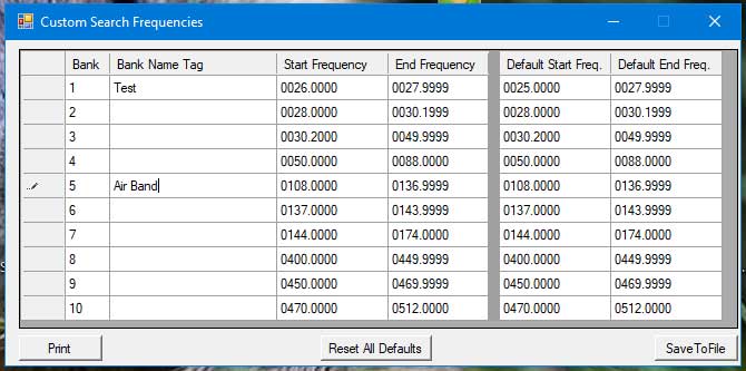
Grid Columns / Data Fields
The column/field details (left to right) are as below:
The following columns/fields are always accessible:
- Row Header - this is a blank non editable field used to select
a row in the grid.
- Bank - this is a fixed named non editable field.
- Bank Name Tag - this is an editable field allowing you to name
a bank. Note! This is a program specific function
only. The scanners do not support bank naming. However any
name you give a bank will be saved and loaded by the program.
Additionally the bank name will be shown on the main control panel and
appear as a pop-up when you mouse hover over that bank on the main
control panel form.
- Start Frequency - this is an editable field allowing you to
enter a frequency. The format is nnnn.nnnn MHz. Any
entered frequency is check for an Out of Band value. Start
Frequency must be greater then the End Frequency. Entered
values are sent to the scanner.
- End Frequency - this is an editable field allowing you to
enter a frequency. The format is nnnn.nnnn MHz. End
Frequency must be greater then the Start Frequency.
Any entered frequency is check for an Out of Band value.
Entered values are sent to the scanner.
On the right of the form is a quick reference table of the Default Start and
End Frequencies for the bands. These are what will be set if a Reset
All Defaults is made.
Save To File Button
A file save dialogue will be show. All the 10 banks of data
will be saved to the file of your choice. This Save To File is
a PART save file as marked with "#part#" in the header and
when the file is reloaded it will only update those scanner settings as
defined in the file.
Print Button
A printer dialogue will be shown where you can select the required printer
and printer properties to print the information.
Reset All Defaults
A confirm dialogue will be shown. Selecting OK will result in the all
the Custom Search values being reset to their default values. Any
attached scanner will also be updated with these default values.
The default values set will depend upon the model of scanner attached.
Services Search Bank Settings Group
This gives access to Setting scanner's Services Search Banks.
These operate differently to the previous Scan and Search Bank check
boxes.
These do not select each of the scanner's service banks to be
enabled or disabled for when the scanner is scanning in Services Search
Mode. Instead all they do is to defined if that bank has Delay
ON or Scan Down setting applied to it.
NOTE! The scanner only scans one service bank at a time wrapping
continuously until another bank is selected. To select another serice
bank then hit click the Hold button and then click the SVC
button. This will cause the scanner to scan the next Service Bank.
The number of banks and their names depend upon the scanner attached.
UBC75XLT and AE75H have 7 fixed banks available which are
named: Emergency, Freenet, PMR, Marine,
Air Band, CB Radio, HAM Radio.
BC75XLT and SR30C have 10 fixed banks available which are
named: Weather, Police, Fire/Emergency, Marine,
Racing, Civil Air, HAM Radio, Railroad, CB Radio, FRS/GMRS/MURS
Scanner Virtual Console Group
Scanner Virtual Console is virtual representation of the
scanner's display and support for the key scanner buttons that one would
normally press when scanning.

Scanner Display
IMPORTANT INFORMATION - Please read carefully
This Virtual Scanner Display is Scan75's interpretation and construction
from exceptionally limited information available from the scanner over the
USB interface regarding it's screen content. The only information
that the scanner sends is:
- Frequency
- Modulation
- Squelch status
- Mute status
- Signal strength
This means that the Scan75 program has to build and decode all the other
display information from the above four pieces of information supported by
what program actions you take. e.g. Start a Scan, Hit Hold, Up, Down
and so on.
This means that it is very important that when using Scan75 you ONLY
interface and operate the scanner directly from the Scan75
program. Failure to do so will mean that Scan75 will not know
what you did and will lose track of the scanner status apart from the
above listed four pieces of information that the scanner sends.
The orange scanner display is a dynamically constructed from very limited
information from the scanner, actions you take via the program's control
functions and program data processing.
This display supports the basic 5 line display as provided on the scanner
but does not support the graphic character symbols that the scanner display
can display. Instead these graphic symbols are replaced with
meaningful text strings as detailed in the table below (where supported).
In addition the display has a 6th line on which the Scan75 program will
display additional information derived from processing the limited scanner
real time data and analysing program status coupled with additional scanner
data or known channel frequencies, e.g. mapping a marine frequency to a
marine channel number.
| Display Line No. |
Graphic Symbol Description / Text |
Replacement Text |
| 1 |
Reverse Video PGM text |
PGM |
| 1 |
Key Lock symbol |
Key |
| 2 |
Reverse Video F symbol |
F |
| 2 |
Scan Up Arrow symbol |
> |
| 2 |
Scan Down Arrow symbol |
< |
| 2 |
DLY |
DLY (not supported) |
| 2 |
Close Call Priority symbol |
(C) |
| 2 |
Close Call DND symbol |
[C] |
| 2 |
Battery Meter symbol |
Bat |
| 2 |
T |
T (not supported) |
| 2 |
L/O |
L/O (not supported) |
| 3 |
P |
P (not supported) |
| 3 |
Priority PRI symbol |
PRIi |
| 3 |
Priority PRI+ symbol |
PRI+ |
| 3 |
Priority PRI in Reverse Video symbol (DND) |
DND |
| 4 |
SCAN EMG FRN PMR MRN AM |
SCAN EMG FRN PMR MRN AM |
| 5 |
HOLD AIR CB HAM FM |
HOLD AIR CB HAM FM |
| 6 |
Scan75's decoded extra information |
Channel Information Etc. |
| 7 |
Virtual Channel / Frequency Alpha Tag Name |
Virtual Chan/Freq Alpha Tag Name |
Due to using the replacement text strings to replace the scanner's more
compact graphic symbols it has been necessary to slightly vary the size of
the virtual display lines and of the font size used to ensure that no data
is lost out of view.
In addition to this normal Scanner Display there are also a Big
Scanner Display and a Ribbon Display.
Channel Information
As mentioned above the only information that the scanner provides is
Frequency, Modulation, Squelch, Mute and Signal strength.
Scan75 creates Channel Information by using Frequency and
Modulation together with the type of scan to lookup the equivalent channel
numbers you may have stored or known services information.
The Channel Information will be as follows:
Scan75 will use the frequency and
modulation to find the matching programmed scan channels in the Scan Banks
enabled for active scanning. Examples:
Chan 005
Chan 001 123 150 200
Scan75 will use the frequency to identify
the Service Band. It will then use the frequency to identify
any known CB, Marine, Freenet, PMR, GMRS/FRS or Weather (WX) Channel
for that service band. Examples: (all 75 model variants and SR30C
included)
Srvs Emergency
Srvs Civil Air
Srvs Amateur Radio
Srvs CB CB21
(US/EU)
Srvs CB CB34UK
(UK)
Srvs Marine MAR08
Srvs Marine MAR05r (receive)
Srvs Marine MAR07t (transmit)
Srvs Freenet FRN05
Srvs Other GMRS 06 (GMRS/FRS)
Srvs Weather WX01
Scan75 will use the frequency to identify
the enabled Search Bank in which this frequency is found. It
will then use the frequency to identify any known CB, Marine, Freenet,
PMR, GMRS/FRS, Weather (WX) Channels: Examples are as above for
Services except Srvs is Replaced by Srch Bank n.
Srch Bank 1 CB 39UK
Srch Bank 9 GMRS 22
Srch Bank 7 MAR12
Virtual Channel-Frequency Alpha Tag Names
The scanners supported by Scan75 do not support Channel Alpha/Tag
Names. However like Scan75's support for Virtual Bank Tag Names the
program supports Virtual Channel and Frequency Alpha Tag names. The
user defined alpha tag name will be displayed on line 7 of the virtual
display.
This is done via the user editable frequency_tags.txt file in
the program's install location.
The file format is:
! Scan75 Frequency Tags File - #scan75#
! -------------------------------------
! You are free to edit this file with your frequency,tag names. (CSV
format)
! Comments must start with an ! mark. Frequency,Tag formats are free
but frequency MUST contain a decimal point:
! nnnn.nnnn , nn.nnnnn, n.nnn, n.n, n. etc MHz formats!
! Frequency is matched by presence of 'your' frequency string in the
current scanner frequency.
! Up to 1000 frequency entries my be defined.
0000.0000,This is a Test Frequency Entry.
0122.1,Bingo
You can define variable length frequencies e.g. 125. MHz or 0125.1
MHz or 125.25 MHz or 125.256 MHz and so on. 1000 entries are
supported which are loaded into memory for rapid searching. Any
match/hit is done against the first found entry. As this is
frequency based then SCAN, SEARCH and SERVICES frequencies are
located.
By supporting variable length frequencies you can define the resolution of
the "match/hit" for any given frequency and associated tag name.
This can get round step issues. e.g. in the US they only currently
use 25 MHz steps for civil airband whereas in the UK/EU 25, 12.5 and 8.33
are all in use.
At the moment entries are limited to 1000. If you only define 250
then the lookups will be faster. Depending on performance we could
allow more than 1000 entries.
The other added advantage of the side file approach is that the Services
and Search Scans will be able to pickup and tags the user has defined.
This would not be possible if we had put the tags in the scan banks.
RSSI Signal Strength Meter and Sensitivity Adjustment -
(At Very Top)
The signal strength meter bar is an UN-calibrated indication of signal
strength in the range from 0 to 10 discrete levels. The scanner does
not provide any information that directly corresponds to it's own display
signal strength meter. Instead Scan75 has to interpret a raw and
UN-calibrated Received Signal Strength Indicator
value obtained from the scanner.
Depending on your aerial and levels of signals and noise in your reception
area you may find that Scan75's signal strength meter is too sensitive or
not sensitive enough.
The sensitivity of the meter can be adjusted by left mouse button clicking
the meter display bar. On doing so you will see:

Any adjustment made here will be saved and restored each time the program is
run.
It is not possible to adjust the meter sensitivity from the Big or Ribbon
scanner displays.
Direct Frequency Tuning
This function allows you to use your scanner more like a traditional
communications receiver.
To directly tune to a frequency then left mouse click any of the Virtual
Display display lines. When this is done the following Direct
Frequency Tune form/control will be shown.

The frequency should be entered in MHz and in any of the following forms:
- 128
- 128.
- 128.0
- 128.00
- 128.000
- 128.0000
- 0128 etc
Once entered click the ENTER button or press the PC's keyboard ENTER key.
The scanner will immediately tune to the entered frequency. The
modulation mode (AM, FM, or NFM) will be set as defined by the scanner's
operating Band Plan and frequency range.
If the Automatic Air Band Correction Option is set then
the scanner will tune to the corrected airband frequency.
Big Scanner Display
To enable this display then left mouse button click the Bearcat
Label.
When enabled this will open a separate and larger duplicate scanner display
with "On Top" properties. This big display can be resized or
minimised. This big display will allow the easier monitoring of the
scanner display from a distance. As with the program's other forms
this big display can be docked anywhere on the screen.
The display also has the following control functions:
- Scanner HOLD/Release - Left mouse button clicking any of the
display fields will alternately initiate a scanner HOLD or HOLD Release
- Main Control Panel Minimise/Normalise - Right mouse button
clicking the top display field (RSSI Signal Strength) will alternately
minimise and normalise the main scanner control panel
- Volume Slider - Adjust the scanner volume level. Right
mouse button clicking the slider will toggle Volume OFF and ON.
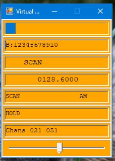
Ribbon Scanner Display
To enable this display then right mouse button click the Bearcat
Label.
When enabled this will open a separate and large ribbon scanner display with
"On Top" properties. This ribbon display can be resized or
minimised. This ribbon display will allow the easier monitoring of the
scanner display whilst doing other work on your PC. As with the
program's other forms this ribbon display can be docked anywhere on the
screen.
The ribbon also has the following control functions:
- Scanner HOLD/Release - Left mouse button clicking any of the
display fields will alternately initiate a scanner HOLD or HOLD Release
- Main Control Panel Minimise/Normalise - Right mouse
button clicking the left most display field (RSSI Signal Strength) will
alternately minimise and normalise the main scanner control panel
- Volume Slider - Adjust the scanner volume level. Right
mouse button clicking the slider will toggle Volume OFF and ON.

Bearcat Button Group
Squelch Indicator
The squelch indicator will turn Green when the squelch is Open.
Bearcat Label
The Bearcat label has two functions:
- To enable the Big Scanner Display when clicked with the left
mouse button
- To enable the Ribbon Scanner Display when clicked with the
right mouse button
Mute Indicator
The mute indicator will turn Green when mute is in operation.
Store Button
The Store button is only enabled when the scanner is in Custom
Search Mode or Services Scan Mode. When the button is
pressed the following things happen:
- The current frequency and modulation are stored to a temporary buffer
- If the current frequency and modulation are already stored then a Duplicate
Store Dialogue is displayed showing the channel number of the
first duplicate found. You can "OK" to continue or "Cancel"
- The button turns green to indicator that there is now a Store
action pending
- The button text turns to Canc (for Cancel)
- The Scan Channels View/Edit screen is displayed ready for you to
complete the store process
- A Store Information Message box is displayed confirming the
frequency and modulation to be stored
You can now complete the Store as described here.
To Cancel a pending store then just press the button again.
L/O Lockout Button
The L/O button performs a Lockout and Unlock with a
single press as follows:
- If the scanner is in Scan mode and the channel is unlocked then it
will be locked
- If the scanner is in Scan mode and the channel is locked (L/O) then it
will be unlocked
- In both cases the View/Edit Scan Banks table and scanner are updated
- If the scanner is in Search or Services mode and the frequency is
unlocked then it will be added to the Global Frequency Lockout
list
- If the scanner is in Search or Services mode and the frequency is
locked then it will be removed from the Global Frequency Lockout
list
- In both cases the View/Edit Global Frequency Lockout table and scanner
are updated
TL/O Temporary Lockout Button
The TL/O button performs a Temporary Lockout and Unlock
with a single press. There is no program related data to be
updated and TL/Os are local to the scanner only.
The TL/O button performs two functions:
- The TL/O button performs a Temporary Lockout with a single
Left mouse button click/press. There is no program
related data to be updated and TL/Os are local to the scanner only.
- The TL/O button enables/disables the program's Automatic
Temporary Lockout with a single Right mouse
button click/press. When Automatic Temporary Lockout is enabled
the TL/O will turn Yellow to indicate this enabled state.
TL/Os only last for the duration the scanner is powered ON.
TL/Os can not be listed. Powering the scanner off and on
again will clear all TL/Os.
The Automatic Temporary Lockout function will be useful when you
wish to profile/log new transmissions only. To avoid unwanted
Automatic TL/O operation the state off the function is NOT saved on
program closure. Automatic TL/O will be off/disabled when the program
starts.
Mode Button
The Mode button changes the reception mode of the scanner.
When the scanner is receiving an AM signal (i.e. in AM mode) then
the button text will display AM. Pressing the button will
switch the scanner reception mode to FM and the button will display
FM. Similarly for FM to AM changes.
Note 1 - reception mode changes may be blocked by certain scanner Band
Plan limits
Note 2 - this button is disabled if a BC75XLT or SR30C scanner is
being used as these scanners do not support direct reception mode changes
Scan Control Button Group
These buttons directly control the scanners scanning.
Scan, Srch and Svc Buttons
- Scan - will start a Scan Channels scan. The
button will turn Green when scan is active. The button will turn
Pink if scan is in Hold
- Srch - will start a Customer Search scan. The
button will turn Green when search is active. The button will turn
Pink if search is in Hold
- Svc - will start a Services Search scan. The
button will turn Green when a search is active. The button will
turn Pink if search is in Hold
It should be noted that the Services Search scan operates differently to the
Scan Channels and Custom Search scans. Services search scans are
sequential and only one service at a time. Clicking the Svc
button for the first time will start/recomence the last service scan that
was run. Click the Svc button again with casue the scanner to
jump to the next Service for scanning. Repeated clicking will cycle
throught the services. To resume a current Service scan process in
Hold then click either the < (Scan Down) or > (Scan Up)
buttons.
< (Scan Down) and > (Scan
Up) Buttons
These buttons perform the same function as the scanners scroll wheel
when in scan/search mode.
- < - will start or change direction of current scan/search to
a downwards direction
- > - will start or change direction of current scan/search to
an upwards direction
- (Step Down) and + (Step Up) Buttons
These buttons perform the same function as the scanner's scroll wheel
when in HOLD mode.
- - - will cause the current channel or frequency to be
decremented by one channel or one frequency step size
- + - will cause the current channel or frequency to be
incremented by one channel or one frequency step size
Hold Button
- Hold - will cause the current scan or search to go into HOLD
mode. The button colour will turn Red.
To release the Hold then press any of the Scan, Srch, Svc,
< or > buttons.
Bank 1 to 0 Buttons
These buttons perform the same function as the scanners 1 to 0>
buttons when in scan/search mode.
When pressed they do the following:
- Select and Deselect that numbered bank
- Turn Green if that numbered bank is currently enabled for the current
scan/search
Autoscan Check Boxes: A-Scan / A-Srch / A-Svc
Each of these automatically initiate/start a Scan or a Search
or a Services scan when the program starts.
Normally the scanner will be put into a Scan HOLD state when the
program starts. By selecting one of the Autoscan check boxes
then the chosen scan action will be initiated immediately after the program
starts.
This Autoscan ability can be used in conjunction with the Auto
Log, Auto Save and Automatic Record function to enable
one to use Scan75 in a scheduled manner (via Windows Task Scheduler)
to capture activity unattended at any time of day or night. To
do this use the Scan75 program to select the Scan Banks/Channels or the
Search Banks/Frequencies or the Services Banks, set any other functions and
options and then check/select the appropriate A-Scan, A-Srch
or A-Svc action and then close the program. Leave the scanner
powered on in HOLD mode and the PC running. When the Windows Task
Scheduler starts the Scan75 Control Program at your chosen date and time
then Scan75 will get on and do what you have set it to do.
Program Latency - Average Status and Display Refresh Time

This upper time display shows in milliseconds the actual average
time in any given 1 second period the program takes to do the following:
- Get all required status data from scanner
- Analyse said data
- Build and display the virtual scanner display.
A warning sound may be issued and the background colour changes as follows:
- If Status Poll Time is less than this time then colour goes RED and a
system exclamation sound is issued.
- If Status Poll Time is greater than this time then colour goes ORANGE.
- If Status Poll Time is TWICE this time then colour goes GREEN.
(recommended setting)
The lower time display shows the Status Poll Time which
by default is determined by the program.
The lowest label says whether Auto or User status
interval polling is in use and the COM read method. The default COM
read method is RL (READLINE) but can changed via the Scan75-ini.ini file
to RE (READEVENT) for the next program run only. Contact program
author for further information.
The Status Poll Time refresh period can be user adjusted on the Options
Panel from 5ms to 1000ms. It defaults to a high
300ms. Unless you experience problems then you should always use the Auto
Status/Refresh setting on the Options Panel.
If manually setting the Status Poll Time then it should be set for GREEN for
reliability and command responsiveness. For more modern PCs / laptops then a
poll time setting of 20ms to 50ms should be achievable.
Running with ORANGE is normally OK. Running in the RED will cause user
interface command issues as the program is spending all it's time attending
to status and display duties.
Clock Display Group
The Clock Display shows the current Local and GMT/UTC date and
time. These are taken from your PC's Time Zone and Date and Time
Settings.
The current selected time for logging (as set in the Options) is shown with
a light green background.
It is not possible to adjust these times with the Scan75 Program.

Notepad and Auto Save Group

The program has a built Notepad and Autosave functions.
When the View/Edit button is pressed a new Notepad
Log and Auto Saved Frequencies form is opened.
When the Log Current is button pressed then the current frequency
and reception mode of the scanner, along with the date and time are added to
the Notepad Log. Depending on the settings on the Notepad
Log and Auto Saved Frequencies form a number of actions may take
place.
Notepad Log and Auto Saved Frequencies

This form is split into two main components. A Notepad Group
on the top and an Auto Saved Frequencies Group on the bottom.
The Date and Time entries will be in either GMT (23/09/2014,13:48:55,GMT)
or Local time (23/09/2014,13:48:55,LCL). The logging of time in
GMT or Local time is determined by the Notepad Settings.
Both groups have Goto Top and Goto Bottom buttons which will
scroll the relevant data views to the top and bottom of their respective
data views. No further detailed explanation required.
If either the Notepad Auto Log function and/or the Auto Saved
Frequencies function are enabled then frequency data will be
stored/added to the file called "scan75-frequency.log"
Notepad Log Group
This Notepad information is stored in a file called "scan75-notepad.txt"
and this will be located in the program directory or where you have chosen
to locate your other scanner data files. It is capable of storing 2048
MB of data. The data will be loaded and saved when the program starts
and ends. The current Notepad usage in Bytes/KB/MB is displayed at the
top of the Notepad area. You will receive a program warning when the
currently stored data in the file exceeds 5 MB. When you start to
receive these warnings then you should ideally backup your data as soon as
possible and then use the Clear Notepad function.
Loading and saving data exceeding 5 MB will slow down the program start and
shutdown performance.
The entries in the Notepad are in CSV format as follows:
03/05/2021,18:22:12,LCL,0125.0000, AM,10,AE,AS OLD=002,Chan 024 054
03/05/2021,18:22:15,LCL,0128.6000, AM,03,AE,AS OLD=018,Chan 021 051
03/05/2021,18:22:27,LCL,0144.0000, FM,05,AE,AS NEW=019,Srch Bank 7
03/05/2021,18:23:09,LCL,0028.6850, FM,07,AE,AS NEW=020,Srch Bank 2
03/05/2021,18:24:00,LCL,0113.3500, AM,06,AE,AS NEW=021,Srch Bank 5
03/05/2021,18:25:24,LCL,0129.4250, AM,03,AE,AS NEW=024,Srch Bank 5
03/05/2021,18:25:34,LCL,0135.3666, AM,01,AE,AS NEW=025,Srch Bank 5
03/05/2021,18:25:47,LCL,0118.3000, AM,01,AE,AS OLD=001,Chan 001
03/05/2021,18:26:04,LCL,0144.0000, FM,06,AE,AS OLD=019,Srch Bank 7
03/05/2021,18:26:20,LCL,0149.9937, FM,09,AE,AS OLD=017,SRCH Bank 7
03/05/2021,18:27:06,LCL,0149.1000, FM,09,AE,AS NEW=026,Srvs Freenet FRN 05
03/05/2021,18:27:13,LCL,0446.0062, FM,09,AE,AS NEW=027,Srvs PMR PMR01
03/05/2021,18:27:18,LCL,0446.0187, FM,09,AE,AS NEW=028,Srvs PMR PMR02
03/05/2021,18:27:25,LCL,0161.8750, FM,09,AE,AS NEW=029,Srvs Marine
03/05/2021,18:27:28,LCL,0157.3000, FM,09,AE,AS NEW=030,Srvs Marine MAR26r
03/05/2021,18:27:37,LCL,0113.3500, AM,07,AE,AS OLD=021,Srvs Civil Air
03/05/2021,18:27:43,LCL,0027.5350, FM,07,AE,AS NEW=032,Srvs CB
03/05/2021,18:27:48,LCL,0029.9900, FM,07,AE,AS NEW=033,Srvs HAM Radio
03/05/2021,18:27:54,LCL,0085.6950, FM,07,AE,AS NEW=034,Srvs Emergency
03/05/2021,18:27:59,LCL,0149.0875, FM,07,AE,AS NEW=035,Srvs Freenet FRN 04
03/05/2021 18:28:51 LCL,0000.0000,---,--,--,-- -------,Shutdown(max=439,min=190)
The fields are date,time, local (LCL) or GMT,
frequency, modulation, signal strength (00-10), AE
(if enabled), AS field (if enabled) and either an OLD=nnn or
a NEW=nnn entry where nnn is the Autosaved Location,
and Channel Information.
The Channel Information will as detailed in Channel
Information.
The signal strength is Scan75's uncalibrated signal strength value,
as displayed at the top of the virtual console display and ranges from 00 to
10.
The AE denotes an Auto Entry added automatically by the
program.
The AS denotes an Auto Saved entry added automatically by
the program with either a NEW=nnn or OLD=nnn where nnn
is the Autosaved Location.
The Startup entry is when the current program run was started.
The Shutdown entry is when the current program session run
ended. The (max=nnn,min=nnn) is the maximum and minimum
uncalibrated raw signal strengths received during the session. A
(max=000,min=0-1) indicates that no signals were received during the last
session.
To manually make a new Notepad entry then double click in the
notepad text area and a new record will be created for the current reception
data. To this entry, or any other entry you can add your own
text.
Auto Log Checkbox
This check box, when checked, will enable the Notepad Auto Log function.
When
scanning or searching and the scanner hits and active frequency and the
Squelch opens then the current date, time, frequency,
modulation and signal strength are automatically entered into
the Notepad area together with an AE (auto entry) additional
tag.
Clear Notepad Button
This will clear the current Notepad of all data. Please ensure
you have backed up/copied this data as appropriate. You will be given
a confirmation dialog and option to cancel the clear request.
Auto Saved Frequencies Group
Auto Saved consists of 200 separate storage locations where "hits"
can be automatically saved. This information is stored only in the
program's scan75-ini.ini file. Any of your personal scanner
saved data files will not contain these autosave frequencies.
Auto Saved Quick Tune and Store
Any stored entries can be "Quick Tuned" by mouse double clicking any
particular entry. The scanner will be tuned the the relevant frequency
and modulation. Should you wish to Store this frequency to a
particular Scan Bank and Channel then use Store Button
and complete the store process.
Auto Save Checkbox
This check box, when checked, will enable the Auto Save Frequency function.
When
scanning or searching and the scanner hits and active frequency and the
Squelch opens then the current date, time, frequency,
modulation and Hit Count are automatically entered into the
next available Auto Saved location together. The received signal
strength is not recorded in the Auto Saved location. In
addition an AS (auto saved) additional tag is added to the
reciprocal entry the Notepad area. This AS entry will be
supplemented with either a NEW=nnn or and OLD=mmm
entry. These entries show if the frequency and modulation mode are NEW
and have been stored in location new nnn or they are OLD and
were previously stored in an old mmm location.
Once the Auto Saved data/locations reach 200 then the entries will wrap back
to location 1 thus overwriting previous data. It is your
responsibility to manage these special 200 locations/data.
Clear Auto Saved Button
This will clear the current Auto Saved locations of all
data. Please ensure you have Stored any entries you wish to
keep to an appropriate Scan Bank and Channel. You will be
given a confirmation dialogue and option to cancel the clear request.
Frequency Log File and View Form
If either the Notepad Auto Log function and/or the Auto Save
Frequencies function are enabled, or you initiate a "Log Current"
action then frequency data will be stored/added to the file called "scan75-frequency.log".
This log is cumulative and can be user edited or deleted.
Frequency Log File View Form

This is opened either by the View Freq Log button on the Notepad
Log and Autosaved Frequencies form or by pressing the keyboard
[CTRL] button and clicking the Notepad and Autosave Group's View/Edit
button on the main control panel.
The Frequency Log File View Form allows the Frequency Log File to be
viewed.
The log file is opened as a snap shot ready only view. Any additional
updates to the file will not be loaded unless the form is Refreshed
or the form is closed and re-opened again.
Refresh Button
This will reload the whole frequency log file again thus picking up any
additional updates made since the form was first opened.
Auto Refresh Combobox
The Auto Refresh allows the form to self refresh at defined intervals.
The available intervals are: 0, 5, 10, 30, 60, 120, 180 and 240
seconds. (see notes below)
NOTES!
- An interval setting of 0 turns Auto Refresh OFF and is
the default value when the form is opened.
- Auto Refresh can only be enabled if the size of the frequency
log file is less then 2 Megabytes. This restriction is
done for performance issues associated with the continual reloading of a
large log file. A 2MB file will still contain over 24,000
entries/hits.
- Manual Refresh will always reload the log file of any size.
Frequency Log File Details
File is named "scan75-frequency.log". This log is
cumulative and can be user edited or deleted. There is no size
restriction on the file however when using the program's Frequency
Log File View Form then the Auto
Refresh function is limit to a file size of 2 Megabytes or
less.
The log file is a simple CSV file with entries as follows:
      [Scan],08/06/2017,11:34:32,GMT,0124.9250, AM,00000,06,001,dupe test       ,00032
      [Scan],08/06/2017,11:34:35,GMT,0121.0250, AM,00000,05,002,Sothampton Tower,00036
      [Scan],08/06/2017,11:34:38,GMT,0357.0250, AM,00000,05,004,                ,00050
      [Scan],08/06/2017,11:34:59,GMT,0118.0500, AM,00000,03,001,CB UK Channel05 ,00004
      [Scan],08/06/2017,11:35:04,GMT,0357.0250, AM,00000,05,005,                ,00050
      [Scan],08/06/2017,11:35:46,GMT,0357.0250, AM,00000,05,006,                ,00050
      [Srvs],08/06/2017,11:36:04,GMT,0156.5500, FM,00000,02,001,Marine          ,CH11
      [Srvs],08/06/2017,11:36:10,GMT,0156.6000, FM,00000,03,001,Marine          ,CH12
      [Srvs],08/06/2017,11:36:50,GMT,0156.5250, FM,00000,03,001,Marine          ,CH70
      [Srch],08/06/2017,11:37:34,GMT,0026.9000, AM,00000,09,001,SEARCH BANK1    ,
      [Srch],13/02/2020,17:59:35,LCL,0125.1000, AM,00000,02,004,#My Test Airband,00083
      [Srvs],13/02/2020,18:38:15,LCL,0125.1000, AM,00000,02,004,#My Test Airband,00083
      [Hold],14/02/2020,15:20:14,LCL,0110.6750, AM,00000,02,001,SEARCH BANK5    ,00000
      [Hold],14/02/2020,16:48:34,LCL,0027.1050, FM,00000,00,001,CC1--24/01/2016 ,00052
The fields are scan_type, date,time, local (LCL) or GMT,
frequency, modulation, signal strength (00-10), hit
count (000-999), and Channel Information.
If a SCAN scan is currently active then the scan_type = [Scan]
If a SEARCH scan is currently active then the scan_type = [Srch]
If a SERVICES scan is currently active then the scan_type = [Srvs]
If HOLD is currently active then the scan_type = [Hold]
The Channel Information will as detailed in Channel
Information.
The signal stregth is Scan75's uncalibrated signal strength value,
as displayed at the top of the virtual console display and ranges from 00 to
10.
The hit count is a count of the times the given frequency has been
encountered.
If the count = 0 then this a frequency that has been logged when the Auto
Saved Frequencies function is NOT enabled.
If the count is 1 or greater then the frequency was logged when the Auto
Saved Frequencies function was enabled.
As the log is cumulative all logged frequencies encountered may or may not
appear in the current Auto Saved Frequencies table depending on when
the table was last cleared or the storage locations wrapped.
Apart from writing data to this file the program does nothing else with
the data. The data is intended for use by anyone interested in
analysing the gathered data.
ScannerFTP.html File (HTML Frequency Monitor File)
Scan75 can optionally create an HTML Frequency Monitor
File called ScannerFTP.html which resides in Scan75's program
directory.
This HTML file contains information regarding the Current Frequency being
monitored an optionally the previously monitored frequency information.
See Options for the controls available for this file.
The primary purpose of this file is to allow Scan75 to document, in HTML
format, information regarding the currently monitored and previously
monitored frequencies. This is so that people who feed/broadcast their
scanner's audio output via audio streaming programs, such as Zello, can also
provide a web page which tells their listeners what they are currently
listening to.
I have also written a small AutoFTP utility that can be used to monitor this or
any other file and FTP the file when it changes to a location of the
user's choice.
Current Channel.txt File (3rd Party / RRUK
Linker File)
Scan75 can optionally create a Current Channel
Monitor File called Current Channel.txt which resides in Scan75's
program directory.
This file is updated whenever the frequency changes and Squelch opens.
The file name is chosen to be the same as that which Proscan
software uses and the frequency is in the same CSV Field 4 which the RRUK
Linker program reads.
File Format / Contents are:
program name &
version, ,screen tag name,frequency,modulation, , , ,
e.g.
Scan75
V3.5.0.1 ,
,Air-Air ,0124.7833,AM
, , , ,
If you are a RRUK User please see RRUK's program information on using the
"Current Channel.txt" file.
Note! RRUK is a subscription service and operate completely
independently.
Audio Record and Player Group
The Audio Record and Player Group contains the controls and options
for the program's ability to record and playback recorded sound.
Before detailing the various controls and options a little further
information is required about the basic sound implementation used by this
program. There are also options to change the recording file naming
convention and the quality of the recoding in "Recording
File Name Header and Quality".

PLEASE NOTE! It may be illegal to record certain
types of, or even *any*, radio transmission/traffic in your particular
Country, State or Jurisdiction. It is your responsibility to
check the legality of recording any transmission. Whilst
there may be no restriction on recording, the playing of or sharing
that recording with another person(s) or party(s) may be illegal.
The author does not condone, support or otherwise encourage any
illegal activity. This program's recording features must ONLY
be used in compliance with the laws of your particular Country,
State or Jurisdiction.
Sound System Overview
It was never intended that the sound recording and playback functions of
this program would be able to compete with other sound recording and
playback software available. Instead the design focuses on using the
existing resources that will/should already be available on your Windows
system and tightly coupling these to the program thus allowing for a more
closely controlled scanner recording environment and recording control
options.
It is important to understand the following points:
- No sound feed is available over the scanner USB connection so you will
have to plug into the scanner headphone socket to obtain a sound feed
- To record the program uses your default sound card and input feeds on
your system. You need to set these up in your sound card controls
along with the recording volume level
- When setting recording volume level remember that you can also make
adjustments with the scanner's volume level as well, either on the
scanner or via this program's scanner volume level control
- To playback recorded sound files the program uses your default media
player for .WAV files
- All recoding is to WAV files only. Remember to set the
appropriate "quality" in the Options panel "Recording
File Name Header and Quality". As scanner/reception audio
signals are of low quality it is recommended to set a lower quality
level to reduce recorded file sizes. However the BC75XLT
scanner can also receive wide band FM broadcast stations so for these a
higher quality recoding may be preferred
- All sound is recorded to a continuously written WAV file. This
enables the current/last recording (even during recording) to be be
immediately replayed without having to open a specific WAV file.
- All recorded WAV files are automatically saved in the "wav" sub
directory of the program's installation directory. Unlike
with the scanner settings/data files it is not possible to specify a
target location for recorded files
- There is the option to record the WAV files to Sub Directories. See WAV Record to Sub Directories.
- All recorded file names are determined by the program and take the
form either "frequency-modulation-yymmdd-hhmmss-timezone.wav" or
"channel_info-yymmdd-hhmmss-timezone.wav". Details on how
to select which form is to be used and more details on the name formats
can be found in "Recording File Name Header and
Quality".
- I thought long and hard about the file naming convention and this is
the only one that captures the details of the recording and also allows
sorting by frequency and date and time ordering
Record/Play Controls
These consist of four buttons. Record, Play, Pause
and Stop. Just to the right of these are two information
lines.
The top/first line displays the current status, this being Stopped
(in black), Recording Paused (in Red) or REC with the
recording input source, sample rate, sample bits and stereo/mono (in red),
e.g. REC MIC Input @11025/16/S.
The second/bottom line displays nothing/blank if status is
Stopped. If recording then the root name of the file for the
recording is displayed. Depending on the Options settings then this
is either the frequency and modulation, e.g. 01180000-AM.wav or the
channel/service information, e.g. Chan_001_01183000-AM.wav (in red).
All buttons start with neutral colours. Only the Record
and Play buttons are initially enabled.
Please read the functions of these buttons taking into consideration the Automatic
Record/Settings/Options which can override/take control of the
buttons.
Record Button
The Record button when pressed will turn Red and become
disabled, recording of the current audio sound stream will start.
The Pause button will turn Yellow and become enabled.
The Stop button will turn Grey and become enabled. The Play
button will be disabled. The recording can be paused or
stopped. Please Note! Unless the Split check
box/function is enabled then the current recording will have a file name
starting with the initial frequency the scanner was tuned to when
the recording first started.
When recording then the program will write a Recording.txt file
in the program's directory. This file is for use by another program
and contains:
path\audio_file_name, sample_frequency,sample_channels,sample_bits
The path and file name are determined as per the Options Record to
Sub Directories and the Options File Name setting.
If not recording then file contains "None".
Examples:
If Scanning Examples:
.\wav\01221583-AM-231224-112557-LCL.wav, 11025, 2, 16
.\wav\scan\Chan_001_01221583-AM-231224-111809-LCL.wav, 11025, 2, 16
.\wav\scan\01515500-FM-231224-112234-LCL.wav, 11025, 2, 16
If Searching Examples:
.\wav\srch\Srch_Bank_3_00327600-FM-231224-112106-LCL.wav, 11025, 2, 16
.\wav\srch\00414750-FM-231224-112330-LCL.wav, 11025, 2, 16
If Services:
.\wav\srvs\Srvs_Emergency_00846750-FM-231224-112151-LCL.wav, 11025, 2, 16
.\wav\srvs\00843750-FM-231224-112406-LCL.wav, 11025, 2, 16
Pause Button
The Pause button will become enabled and turn Yellow when the Record
button is pressed. If pressed the current recording or playback
will be paused and the button text will change to Resume. Subsequent Pause
button presses will toggle the Pause/Resume action.
Play Button
The Play is always enabled. The Play button when
pressed will play back the currently recording or the last recorded sound
using your system's default sound/media player.
Stop Button
The Stop button when pressed will stop the current sound
recording. All buttons will revert to their neutral
colours. The Record and Play buttons will remain
enabled.
Automatic Record Settings/Options
These check box settings control how the recording process works. It
is IMPORTANT to understand that these settings can effectively override
your control over the above Record, Play, Pause and
Stop buttons. They are also cumulative in their operation when
selected/checked. They basically work by actively pressing the Record,
Pause and Stop buttons on your behalf and this can result in
a little end user confusion until you are more experienced in using all the
recording and playback functions. It is suggested that you initially
play with these boxes unchecked.
Any selections made will be saved and re-loaded when the program is next
started.
Auto Pause Check Box
When checked and a recording is in progress then whenever the sound is
muted/squelch closed then the current recording will be automatically
paused until the sound is no longer muted and the squelch is open.
This pause/resume record process will continue for all recordings until
this box is unchecked.
When you check the checkbox you will be presented with an Auto Pause
Delay Time selection choice of 0, 1, 2, 3, 4 or 5 seconds. If
you do not change a selection then the form will automatically close with
the last/current selection chosen.
The purpose of the Auto Pause Delay Time is to permit/place quiet
periods between the opening and closing of squelch to avoid abrupt back to
back recordings of transmissions. Choose a value you are comfortable
with.
Note! If you manually pause a recording with the Pause button
and this Auto Pause is enabled then recording will immediately
resume if the current scanner audio is not muted thus overriding your pause
command. This is normal/expected behaviour.
Auto Split Check Box
When checked and recording then every frequency change encountered will be
recorded into a different file with a file name starting with the current
frequency. Whilst scanning, and the scanner is not in Hold status,
then multiple files will be created for every frequency encountered.
It is suggested that for continuity of recording to the same frequency named
file that you set the Search/Close Call delay to 3 or greater.
Auto Record Check Box
This is potentially the most disruptive and confusing recording
option. When checked then whenever the sound is not muted/squelch open
then recording will automatically start. The suggested/preferred
setting for this is unchecked. As this and the other record settings
are saved and restored at program start-up then this setting can be an
issue. However if every time you have your scanner powered on and want
the Scan75 program to automatically go into record mode then this is the box
to check.
Note! If you manually stop a recording with the Stop button
and this Auto Record is enabled then recording will immediately
resume if the current scanner audio is not muted thus overriding your pause
command. This is normal/expected behaviour.
Play Saved Button
This button is specifically for accessing and playing files that have been
previously recorded and saved to the wav directory. When
clicked a file open dialog box will open where you can choose a WAV file to
playback. This playback function uses your default play program for
WAV files and the playback will open in that program's own separate window
and it's controls will then take over. This Play Saved
function is totally independent from the above Record, Play, Pause and Stop
functions and thus you can be actively recording scanner audio whilst also
listening to previously recorded files.
COM Port Control Group
The COM Port Control Group is for managing the communications port
to which the scanner is connected. It consists of the following
components:
- Current Port and Speed Display
- Port Selection Box (not normally required)
- Refresh Ports Button (not normally required)

Note! Currently the program only supports and lists port names named
COMn or COMnn, e.g. COM7 or COM13.
The Scan75 Control Program and the scanners use 57600 baud, 8 data bits, no
parity and 1 stop bit. The Scan75 Program will try to configure any
selected port to these settings. If you experience communication
problems then it is suggested to try setting these values in Windows
- Control Panel - Device Manager - Ports - Port Settings for the
relevant port.
When the Scan75 program starts it enumerates all available COM ports and
adds them to the list of available ports. It will also scan these
ports looking for your powered on scanner. If there are no COM ports
available or the program fails to detect your scanner an error message will
be displayed and the program will enter No Scanner Connected
mode. You will then need to manually select the correct COM port or
close and restart the program.
The program does not support dynamic port detection, i.e. ports or devices
added or removed whilst the program is operating are not
automatically added or removed from the list of available ports. The
program does however have a port Refresh button that performs this
function.
COM Port Display
The COM Port Display shows the currently selected Communications
Serial Port and Port Speed.
It also shows the status of communication as seen by the Scan75
Program. The background light colour indicates the following status:
- RED - There is no selected and valid COM port available on the
system or an error occurred on that port
- GREEN - A valid COM port on the system has been selected and is
operational
COM Port List Box (use not normally required)
When the program starts it will detect all the COMn and COMnn ports
currently available on your PC. It will also search these ports
looking for your scanner. If your scanner is not powered on or the
program fails to find it then you will have to manually select the COM port
yourself.
The COM Port List Box contains a drop down list of all communication
ports that are named COMn or COMnn and are available on your PC.
You should select the appropriate port for your interface.
If you are unsure of which port to use then do the following:
- Ensure your interface is connected to the PC
- Open Windows - Control Panel - Device Manager - Ports and
review the list of ports and most importantly check the names of devices
against each listed port
- Note device names and use the port named Uniden Serial Port (COMn)
COM Refresh Button (use not normally required)
This R button when clicked will cause the program to go through a
port detection routine that will remove missing or invalid ports from the
available port list and add any new ports found.
COM Error Retry Counts
The program supports the following COM error retry strategy.
- Command
Cycle Retry - should either of the Send or Receive cycles fail then the
program will flush all COM input and output buffers and then repeat the
Send/Receive cycle THREE times.
If the program is unable to successfully recover then the program will
display permanent COM error messages.
Battery Voltage Charge Meter

This meter provides both a battery charge indication and a voltage
reading. The meter voltage range from 2.0V to 3.0V is designed to
cover both the use of Ni-MH rechargeable batteries and normal alkaline
cells.
This meter is displayed as follows:
- On program start-up if a scanner is attached and powered on and will
auto close after a default 3 second 'splash' period. Period is
user adjustable.
- For the duration of a mouse hover over the battery voltage display in
the Scanner Controls General Group on the main control panel
For voltages less than 2.30V the meter bar is Red
For voltages 2.30V to 2.69V the meter bar is Orange
For voltages 2.70V and over the meter bar is Green
The length of this 'splash' period on program start-up can be adjusted from
0 second to 5 seconds in the Options Panel. If a value of 0 is
set then no 'splash' will occur on program start-up.
If Ni-MH batteries are being used a voltage of 2.80V or greater indicates a
Fully Charged state. The text "Fully Charged" will be shown
above the OK button to the right of the 2.80V bold marker graduation line.
Note! - Determining an accurate state of charge of Ni-MH rechargeable
batteries under no load conditions is very difficult to achieve. When
the scanner is connected to the USB port then the batteries will be on
charge and thus under no load conditions. If you want to accurately
determine the battery state then you should disconnect the USB cable and
press the scanner's scroll control knob and read the battery voltage, under
load, at the top right corner of the scanner's display.
If alkaline batteries are being used and the scanner's battery compartment
switch is set correctly to the alkaline position then the Battery Voltage
Charge Meter will be displaying the actual battery voltage under load and
can therefore be considered to be accurate.
Automatic Restart After COM Error
The program's default action after a COM/communication error is to STOP,
LOG and display the COM Error Dialogue and await user action. Whilst
COM errors are rare if you leave the program and your scanner running
unattended, e.g. streaming to the WEB or other long term monitoring, then
any COM error is going to be a nuisance.
The program can be configured to perform an Automatic Restart after a
configurable Delay.
To enable Automatic Restart mode then locate the following lines
in the scan75-ini.ini file:
# Automatic Restart After COM Error Setting in ms - 0 OR min of 5000
ini_auto_restart=10000
The minimum restart delay is 5000ms. Anything less than 5000ms will
be taken as 0ms and Automatic Restart will be disabled.
When enabled then at the bottom of the COM Port Control Group you will
see the text Auto Restart nnnnn ms.
Any errors will be logged as usual in the scan75-runlog.log file.
No Scanner Connected Mode
The program is designed to run when connected to a scanner via the scanner's
USB connection. The program will enter and run in No Scanner
Connected mode whenever there are no COM ports available on the system
or a port has not been selected or a scanner is not detected.
When running in No Scanner Connected mode the Title Bar on the form
will also contained the text "No Scanner Connected!" Only
program specific controls will be enabled.

The program will automatically exit No Scanner Connected mode
as soon as a valid COM port has been selected and a scanner is present.
Support, Program Suggestions, Recommendations and Bug
Reports
I welcome support requests, any suggestions, recommendations or bug
reports. These should be sent to:
| scan75 |
@ |
nick-bailey |
. |
co |
. |
uk |
I can not guarantee to fix or implement what you report/suggest but what I
can say is that this Scan75 Program would not be what it is today without
the feedback, suggestions and bug reports that I have received.
Warranty, Liability and License Agreements
The Scan75 Control Program is hereunto referred to as the 'Program'.
In using the Program you are agreeing to accept all of the terms and
conditions stated herein.
The Program is currently Freeware (see http://en.wikipedia.org/wiki/Freeware) with a
Careware/Charity status and objective (see http://en.wikipedia.org/wiki/Careware). It
operates with no limitations.
The author reserves the right to change the program status and limitations
on any future release. Existing releases will retain their status and
your right to use them but support may not be available.
The Program is supplied 'ASIS' and the author neither accepts,
implies nor offers any warranty, liability or any other responsibility for
any damages, loss or other claim of any type in respect of this Program, its
usage or consequence of its usage.
**You use it at your own risk**.
The Program has no guarantee of support or implied right to support.
The Program is the sole Copyright of the author and all rights are
reserved. The author's Copyright is restricted to those files
containing 'Scan75' in their name and any other file clearly written by the
author. The Copyright includes the intended operation, design and
function of the Program. The Program requires other runtime
files to function and the Copyright of these files belongs to their
respective owners/authors.
This product contains Uniden proprietary and/or copyright control
codes. Used with permission.
The creator of this Program asserts that the appearance of the user
interface screens is/are a work of art and therefore attracts Copyright
protection under UK and EU law.
You may not disassemble, reverse engineer or otherwise interfere with any of
the Program executable files.
You may not use this Program for any illegal or unlawful purpose.
You may not sell, rent or otherwise charge for this Program.
The preferred availability and distribution of the Program is from the
authors website to which you and others should refer to.
You may however freely distribute the Program but must do so entirely free
of charge, save for any reasonable charge in respect of any physical media
used in its distribution. All electronic or other non physical media
distribution must be free of all charges. You may not alter, modify,
remove, or in any way change any of the files that comprise the Scan75
Program Control Package as released by the author. You may add your
own text or other information files but these must be clearly identifiable
as yours, added by you and in such a manner that they do not in any way form
part of the Scan75 Control Program or could easily be considered to be part
of the Scan75 Control Program. Neither must they infringe the
Copyrights of any author, person or organisation and must not contain
offensive, illegal or other illicit material.
Should you believe that your version of the Program package has been subject
to any infringement of the above conditions then please contact the author
immediately providing as much information as possible.
Prior to release, the author has to his satisfaction checked that the
Program is free of any Virus or other potentially destructive software/code,
but this is not guaranteed.
Before using the Program you are advised to Virus check the version of the
Program you have prior to using it. The author's Website may also
carry MD5 checksums for the critical files. You are advised to verify
these as well.
You are requested to fully read this and any other documentation prior to
installing and using the Program. In using the Program you are
agreeing to accept all of the terms and conditions stated herein.
The author hopes that you find Scan75 Control Program both easy to use,
reliable and of assistance to you and your Uniden Scanner. He may be
contacted at his Email address and would certainly like to hear of any bugs,
criticism, suggestions etc. that you may have.
Please remember. The Program is supplied 'ASIS' and you use it at
your own risk.
Recognised Trademarks, Proprietary Code and Copyrights
Visual Basic, Windows, Windows XP/Vista/7/8/8.1/10/11, .NET are
registered trademarks of the Microsoft Corporation.
Bearcat is a registered trademark of Uniden Corporation.
This product contains:
- Uniden proprietary and/or copyright control codes. © Uniden
Corporation - All rights reserved. Used with permission.
- Un4Seen BASS Library functions. © un4seen developments - All
rights reserved. Used under license.
- radio24 BASS.NET Library functions. © radio42, Germany - All
rights reserved. Used under license.
Other Trademarks may be mentioned in this document and the author
acknowledges them.
© Nick Bailey 2019-2023