DriveR8 Control Program User Manual 
A program to control the Alinco DX-R8, DX-SR8 and DX-SR9 Communications
Equipment
© Nick Bailey 2016-2023
http://www.nick-bailey.co.uk/driver8
You are requested to fully read this and any other documentation prior to
installing and using the Program.
In using the Program you are agreeing to accept all of the
terms and conditions stated herein.
Manual Version 2.8.0.0 - 22 June 2021
Contents Index
Author and Copyright Information
This program has been written by Nick Bailey and is his sole Copyright.
DriveR8 Control Program © Nick Bailey 2016-2021
 Please
Donate to my supported charity which I would very much appreciate, as
will they, and will keep me developing and supporting the programs.
Please
Donate to my supported charity which I would very much appreciate, as
will they, and will keep me developing and supporting the programs.
The Program is currently Freeware (see http://en.wikipedia.org/wiki/Freeware)
with a Careware/Charity status and objective (see http://en.wikipedia.org/wiki/Careware).
It operates with no limitations. The author reserves the right to
change the program status and limitations on any future release.
Existing releases will retain their status and your right to use them but
support may not be available.
This document may mention DriveR8, DriveR8 Program or DriveR8
Control Program. They are the one and the same and are to be read,
understood and respected as being so and thus covered by the Copyright,
Warranty, Liability and License Agreements detailed here and in Section/Chapter
7.0 of this document.
The creator of this program asserts that the appearance of the user
interface screens is a work art and therefore attracts Copyright protection
under UK and EU law.
This product contains Alinco proprietary and/or copyright control codes.
Used with permission.
My website can be found at http://www.nick-bailey.co.uk
and for this program at http://www.nick-bailey.co.uk/driver8
My contact Email address is in the table below:
| DriveR8 |
@ |
nick-bailey |
. |
co |
. |
uk |
I apologise for munging my Email address but as we all know SPAM is a
major problem and keeping my DriveR8 email address free of spam will help
us all.
Preface
Welcome to the DriveR8 Control Program specifically designed for
controlling the Alinco DX-R8T/E/J, DX-R8T/E/J and DX-R8T/E/J
Communications Receiver/Transceivers.
The DX-R8E is a Worldwide market orientated Receiver
The DX-R8T is an American/Canadian market orientated Receiver
The DX-R8J is an Japanese market orientated Receiver
The DX-R8/9E is a Worldwide market orientated Transceiver
The DX-R8/9T is an American/Canadian market orientated Transceiver
The DX-R8/9J is an Japanese market orientated Transceiver
DriveR8 supports both data management and real time control
of these receivers/transceivers.
As I do not currently have a DX-SR8 or DX-SR9 Transceiver to test against I
have relied on my beta tester (SR8) for confirmation of function and bug
fixing. This means there may be some issues I may have to
resolve. I will only know of these issues if people are kind enough to
let me know what they are.
Alinco model determination is done via that which is encoded in the Alinco
firmware. From there DriveR8 uses information supplied to the Author
by Alinco Japan to determine what functions each Alinco model
supports. I have since found that there my be some "odd" model
configurations out there in the real world and you may encounter and
error. If this happens then *please* contact me and I will do
my best to resolve the problem as quickly as possible.
When reading this manual you will find that some function explanations are "short
and to the point" with little extra information. This is because
the function is self explanatory and fully documented in the Alinco
Instruction Manual.
Please read this manual in conjunction with your Alinco's
Instruction Manual.
PLEASE NOTE! Writing this User Manual requires both
pictures and words and a huge amount of time, time that even commercial
companies are not prepared to invest in.. To keep EVERY picture completely
current with regards to release is not always possible. What you
will see is that function relevant to new release is absolutely 100%
current.
If I've missed, documented incorrectly or totally got it wrong the PLEASE
let me know as WE will work to get it sorted out for the benefit of
all users.
Donate to DEBRA Charity
Please
Donate to my supported charity which I would very much appreciate, as
will they, and will keep me developing and supporting the programs.
The Program is currently Freeware (see http://en.wikipedia.org/wiki/Freeware)
with a Careware/Charity status and objective (see http://en.wikipedia.org/wiki/Careware).
It
operates no limitations. The author reserves the right to change the
program status and limitations on any future release. Existing
releases will retain their status and your right to use them but support may
not be available.
Program Overview
The program is a standalone portable application that only requires
Microsoft Windows and the Microsoft .NET V4.5 platform to be
installed. The program is designed to fully function with an Alinco
attached. Without an attached Alinco then functionality is limited.
The User Interface design has been created to give maximum and easy control
from a single Main Control Panel form. The other important
user interface form caters for the Viewing and Editing of Memory Banks.
Use of other forms/panels has been limited to confirmation dialogues,
error messages, options, file management and other items not frequently
used.
HELP - All control groups, keys, buttons and displays have "Mouse
Over" help prompts. The Menu Help function will display the DriveR8-Manual.html
in your default Web Browser.
Controls and Displays are grouped together into the following main logical
function groups (some of which contain sub groups):
- Display - (includes frequency changing function)
- RF Mode
- RF Step
- RF Settings Main
- RF Settings Other
- Frequency Change Controls
- Memory Tune
- Special Bank X (Special Memory)
- Memory Banks (View/Edit/Store Functions)
- Memory Match Display
- Scan Controls
- Illumination Settings
- Key/Dial Settings
- Power Controls
- Alinco Read Refresh
- COM Port Settings
- Program/PC Clock
- Notepad and Autosave
- Audio Recorder and Player
- Status Latency Display
- SR8 - SR9 Transmitter Settings
- Scheduled Tuning with Optional Recording
The Menu Bar. Besides the typical About and Help
menu items you will find the following additional functions:
- Save Settings
- Load Settings
- Scheduled Tuning
- Reset Colour Scheme
- Options
- COMMENTS Link
- DONATE Link
- Home Page Link
The Memory Banks View/Edit Functions are supported in View/Edit
mode with their own dedicated data entry forms which contains additional
functions like Save To File, Print, Add, Delete, Copy, Move and Find.
The following section clearly shows the Main Panel and a corresponding table
of differences between Alinco models. With these in mind one should
have no difficulty in understanding the differences and relevance of
documentation.
Program Main Panel for DX-R8T/E/J Receivers
The Receiver is tuned on Memory Bank A location 050 with a Name of
SOLENT. The frequency is 1.000500MHz in AM mode with an RF Gain
of +10dB and AGC set to SLOW. Noise Blanker is ON, Narrow Filter is on
NARROW (Nar). RIT is ON and Key/Dial lock settings are DIAL.
Sleep timer is set to 30 minutes with 27 minutes remaining. APO timer
is set to 90 minutes with 87 minutes remaining. The frequency is an
exact match on Memory Bank A Location 50. The Program/PC Clock uses a
green coloured background to indicate the currently set Local or
GMT/UTC setting. All the other settings are also clearly displayed.

Program Main Panel for DX-SR8 and DX-SR9 T/E/J
Transceivers
The Transceiver is tuned with VFO-A to frequency of 5.250000MHz in USB
mode with an RF Gain of +0dB and AGC set to SLOW. This is an [ HF]
60 metres band frequency. Noise Blanker is OFF, Narrow Filter
is on NARROW. RIT is ON. Key/Dial lock settings
are BOTH. APO timer is set to 90 minutes with 86 minutes
remaining. The frequency is an exact match on Memory
Bank A Location 200 and Memory Bank X Location 125.
On the transmitter side then Transmitter Power is set to HIGH and is
currently transmitting (Red USB display and TXMit button). A Split
Frequency of 3MHz is set. PTT Lock is OFF, Speech Compressor is
ALL, Split Frequency is ON, CTCSS if OFF, CTCSS Tone is 91.5 TXIT
and Access in ON.
All the other settings are also clearly displayed.
Note that the Program/PC Clock uses a green coloured background to
indicate the currently set Local or GMT/UTC setting.

DX-R8 and DX-SR8 and DX-SR9 Model Differences
The differences between the Alinco DX-R8/SR8/SR9 (types E/T/J) models with
regards to DriveR8 are as detailed below.
| Item / Function |
DX-R8E |
DX-R8T |
DX-R8J |
| Frequency Range (base) |
135kHz - 29.999999MHz |
135kHz - 29.999999MHz |
30kHz - 34.999999MHz |
| Frequency Range Expanded (model/date variance) |
30kHz - 34.999999MHz |
30kHz - 34.999999MHz |
30kHz - 34.999999MHz |
| RIT |
Yes |
Yes |
Yes |
| TXIT |
No |
No |
No |
| IQ / SDR Support |
Yes |
Yes |
Yes |
| Sleep Timer |
Yes |
Yes |
Yes |
| APO Timer |
Yes |
Yes |
Yes |
| TX Power Change |
No |
No |
No |
| LED RX Colour Change (Green for RX / Red for RX) |
Yes |
Yes |
Yes |
| Transmit Function Support |
No |
No |
No |
| Item / Function |
DX-SR8/9E |
DX-SR8/9T |
DX-R8/9J |
| Frequency Range (base) |
135kHz - 29.999999MHz |
135kHz - 29.999999MHz |
30kHz - 34.999999MHz |
| Frequency Range Expanded (model/date variance) |
30kHz - 34.999999MHz |
30kHz - 34.999999MHz |
30kHz - 34.999999MHz |
| RIT |
Yes |
Yes |
Yes |
| TXIT |
Yes |
Yes |
Yes |
| IQ / SDR Support (SR9 only) |
SR8=No / SR9 =Yes |
SR8=No / SR9 =Yes |
SR8=No / SR9 =Yes |
| Sleep Timer |
No |
No |
No |
| APO Timer |
Yes |
Yes |
Yes |
| TX Power Change |
Yes |
Yes |
Yes |
| LED RX/TX Colour Change (Green for RX / Red for TX) |
No |
No |
No |
| Transmit Function Support |
Yes |
Yes |
Yes |
NOTE!I've had an anonymous comment from a user that their model is a
DX-SR9T but DriveR8 identifies it as a DX-SR9J and DriveR8 errors and fails
to connect (AL~SR_IQM error). This is interesting as all the Alinco
information I have indicates that all SR9 models support the IQ
function. Clearly something is odd here. Firmware saying it is
an SR9J model but machine is badged SR9T and IQ function is not present when
it should be! I need to know about any of these sorts of errors so I
can investigate and correct the DriveR8 software - SO PLEASE email
me if you come across any error!
Program Locale/Region Setting
This program is designed to run in en-GB locale mode where we use
the Full Stop/Dot/Period ( "b>." - ASCII decimal 46) as the decimal
mark/separator character and not the Comma ("," - ASCII decimal 44).
You DO NOT need to change your system's Region and Language settings
to use this program. You will however have to use the Full
Stop/Dot/Period ( "." - ASCII decimal 46) as the decimal
mark/separator character when entering data.
Program and Driver Installation
The program is written as a portable application requiring no installation
program. As long as you have Windows and the .NET V4.5
framework installed then getting the program up and running is simple
Obtaining and Delivery
The program can be obtained from my web site http://www.nick-bailey.co.uk/driver8. Here you
will find program information, download link and MD5 checksum information so
you can validate the integrity of your download. The direct download
link is http://www.nick-bailey.co.uk/driver8/download.
The download will usually consist of a single ZIP file for the program and
all associated files and User Manual.
Driver Installation
To control your Alinco from your PC you will need either the Alinco
ERW-7 Interface Cable or an alternative USB to Serial Interface
Cable. If you do not already have a USB driver installed for your
interface cable then you will have to download and install the appropriate
driver. The Alinco ERW-7 Interface uses the Future Technology Devices
Internationals FDTI Chip for which the driver can be found on their www.fdtichip.com website.
NOTE! The DriveR8 Control Program will try to locate a
powered on Alinco on a USB/COM port does. If the Alinco is not
powered on or the program fails to find the Alinco then you will have to
identify and manually select the correct USB port yourself. See here.
Program Installation
To install the DriveR8 Program is very straight forward. You will have
received DriveR8 in either a ZIP file or as separate files. The
program has no specific install program and does not make registry changes.
Just follow these simple steps.
- Create a directory of your own choice on your PC. It is
suggested to give this directory a name like 'DriveR8 Control Program'
for easy recognition
- Un-ZIP / copy ALL the folders and files to the directory you
have just created. DriveR8.exe will not work on it's own!
- Read the DriveR8-ReadMe.txt and DriveR8-History.txt
files. They have important information
- It is suggested to create a short cut to the DriveR8.exe file
on your desktop or elsewhere
- Optional/Suggested - backup the original distribution file(s) to a
safe location
- Read the DriveR8-Manual.html file to familiarise yourself with
the program
NOTE! It is suggested that you do not place the program in a
system directory like Program Files (x86) or Program Files
etc, as these directories require Administrator privileges and you
will encounter file write errors issues unless you force the program to Run
As Administrator which is not recommended for security and safety
reasons.
Program Patch Installation
There may be times when just a Patch Release EXE file on its own is
released. This EXE file must be installed into the program
directory of a current DriveR8 program installation. The EXE
file will not work on its own. If you are a new DriveR8
user then you must first install the base full release and then
apply the patch.
Removal
The DriveR8 Program can be simply and fully uninstalled at any time.
CAUTION! The following steps will completely remove DriveR8
Program and all your associated data. If you want to keep any
data files you have created then you should move/copy these files to another
directory first.
- Delete the folder you created and all the files
therein
- Delete the short cut you created (if any)
Upgrade Process
Upgrading to a later version of DriveR8 is simple and straight
forward. Upgrading will retain your important configuration
files. Following all the steps of this procedure will also give you a
backup version(s) of the program to revert to should you wish or need to.
Warning! The program will either create or use any existing
configuration files it needs. These files are:
- DriveR8-ini.ini
- DriveR8-cache.ini
- DriveR8-notepad.ini
- DriveR8-frequency.log
- DriveR8-runlog.log
- ReceiverFTP.html
Other files that contain your personal saved data / settings will not be
overwritten by the installation process as they are not shipped with the
DriveR8 Control Program. You are however strongly advised to back
these files up for your own protection, together with any of your own user
files you have created.
To upgrade follow these simple steps:
- Locate your current installation folder
- Create a new sub folder named Vn.n.n.n corresponding to the version
number of your currently installed version, e.g. V1.0.0.9
- Copy ALL the contents of the current installation folder into the new
backup Vn.n.n.n sub folder you just created
- Un-ZIP / copy the new program release files to the current
installation folder and OVERWRITE/REPLACE the existing files
- Read the DriveR8-ReadMe.txt and DriveR8-History.txt
files. They contain important information
- Read the DriveR8-Manual.html for help or details on any new
functions that may have been added
If there are any release specific files or instructions then you will be
notified of these on the web site prior to downloading the program.
Running / Program Start-up
Running the program is a simple matter of invoking the DriveR8.exe
file. This can be done via a Windows shortcut link or by using the
Windows 'run' command.
Running when Connected to a Powered On Alinco
When the program is started and a powered 'On' Alinco is present and
connected to the program's currently configured COM port then the program
will read ALL the Alinco's current settings and data values with
the exception of the MEMO (Bank Main), MEMO A (Bank A) and MEMO B
(Bank B) Memory Banks. These Memory Banks are only read when required
due to the time taken to read each of the banks. However once read
their data can be cached and this data will be used on all subsequent
program runs. Memory Bank X is a special memory bank belonging to the
DriveR8 program and is TOTALLY independent of the Alinco.
All Alinco data read will be used by the program as a "statement of fact"
regarding the Alinco's data state.
Once running then any changes you make via the program will be
sent/committed to the Alinco. Any changes you make directly on the
Alinco, with the exception of a frequency change, will not
automatically be sent to the DriveR8 Control Program. In simple terms
the DriveR8 Control Program is the Master and the Alinco is the Slave.
It is important to understand this Master/Slave operational relationship so
that you do not inadvertently lose data.
Where you do make changes on the Alinco, other than direct memory edit
and store functions, then you can use the Alinco
Read Refresh button to force the program to completely re-read
the Alinco. If you do this then for the duration of the read process
the Alinco is the master and the program is the slave. NOTE!
Any memory changes you made on the Alinco will not be picked up and the
program's cache settings will persist. For the DriveR8 program to pick
these 'direct on Alinco' memory changes made then you will have to use the
each of the program's Memory Bank Edit/View functions and then do a
Read Bank to refresh to update DriveR8's knowledge of those memory
changes.
Running with No Alinco Connected
When the program is started with no Alinco attached, powered on, or
with an incorrect COM port selection then the program will enter No
Alinco Connected mode of operation.. You will have to
power on your Alinco and select the correct COM port manually or close and
restart the program. When a connection is made then the program will
read the Alinco data as defined in the above "Connected" state. See here for information about No Alinco Connected
operation.
Controls and Functions
As already mentioned the Main Control Panel contains all the
essential controls and functions in one easy to understand and navigate
layout. Controls and Functions are grouped in containing titled and
outlined defined areas.
Please Note! The MEMO (Bank Main), MEMO A (Bank A) and MEMO B (Bank B)
Edit/Write functions are disruptive in that the Alinco has to be put
into Alinco Memory Write Mode. Once this occurs then when the
Edit/Write has been completed then the Alinco will go into a PASS
state. This PASS state leaves the Alinco in disrupted state in that
the Alinco's front panel controls will no longer function. However the
Alinco can still be controlled from the DriveR8 program.
All other controls and functions are not disruptive.
Title Bar

The program title bar displays the following information:
- Program Name
- Program Author Copyright and Name
- Program Version Number - e.g. V1.0.0.0
- Program Website URL
- Model Number - e.g. DX-R8E
- Model Version: Model Full Internal Model Identification
Menu Bar
The menu bar is similar to any Windows menu bar. Here you will find:
DONATE
This will allow you to make a donation
to the DEBRA charity. Please do this in appreciation of this
free program and my user support.
Comments
This will allow you to anonymously give any comments you may have about
DriveR8.
About
About provides the following:
- Program Name, Version, Copyright and Author information together with
Warranty, Liability and License Terms and Conditions and other
information.
- Check for Program Update button (manual)
Check for Program Update Button
If you press this button then the program will check your version against
the latest official full version on the DriveR8 website. The response
will look as follows:

Depending on the version you have you will see one of the following
messages:
- "You have the latest version so no update is required."
- "Your version is NOT up to date. V1.n.n.n is now AVAILABLE!"
- "Your version is later than the official version. No update
available."
If you see "Your version is later than the official version. No update
available." then it means that you are running a "special" patch or test
version of the program.
Instead of using this manual check you my wish to enable the Automatic
Program Update Check on the Options menu.
If an update is available then the Information and Download
buttons will be enabled.
Please Note! For both the manual and automatic program update
checks no data (other than the update information) is download or installed
to your PC. If you want the updated version of the program then you
must go and fetch it yourself.
Help
User Manual
This will open the DriveR8 User Manual file DriveR8-Manual.html
in your default Web Browser. Besides this help file you will also
find that all control groups, keys, buttons and displays have "Mouse
Over" help prompts.
Support
This will open the Contact Us web page where you will find the support
Email address for DriveR8.
Save Alinco Settings
This will save all the program's current Alinco settings, memory
data, etc. to a file of your choice. This is in effect a complete
backup/snapshot of all data, all selected states and settings. The
saved data also includes Special Memory Bank X data that is normally stored
in the DriveR8-ini.ini file.
When this file is subsequently loaded then the program will send all the
data, states and settings to the Alinco.
This save is FULL save and the file is marked with "#full#"
in the header. When the saved file is reloaded it will clear and
overwrite all the Alinco's settings.
It it suggested you choose a sensible and informative file name when saving
any data so that you can easily identify what the files contain when you
load them in the future.
Load Alinco Settings
This will load the settings and data in the chosen file into the program and
into the Alinco. The file to be loaded may contain a full
backup/snapshot as made with the Save Alinco Settings menu item or
may just contain data you have previously selected and used the Save To
File function in any of the View/Edit forms.
If the file to be loaded is a FULL save file as marked with "#full#"
in the header, then when the file is reloaded it will clear and overwrite
all the Alinco's settings. The restored data also includes Special Memory
Bank X data that is normally stored in the DriveR8-ini.ini file.
If the file to be loaded is a PART save file as marked with "#part#"
in the header, then when the file is reloaded it will only update those
Alinco settings as defined in the file.
When you load a data file, if enabled, the Autobackup PREVnnnn
function (control via the Options Panel) will first save a copy of
the program's current Alinco data settings to a PREVnnnn file for safety
just in case you have any unsaved work. The autobackup data also
includes Special Memory Bank X data.
Scheduled Tuning
This will open the Scheduled Tuning form where you can set/define
one or more tuning schedules up to a current maximum of 10 schedules.
Details of the settings are below. This is a very useful facility for
tuning to (and optionally recording) news broadcasts, NAVTEX, or just your
favourite radio station program.

Fields Are As Follows:
- Number: This is the schedule number. You can pick a
Start Date on any schedule number row but these will then be re-order in
ascending date and time order on form closure.
- Date: This is the schedule start date. This has to
be defined and on clicking this cell the Date Picker calendar will be
shown from where you can select the required day, month and year.
Note! A strange peculiarity of the Date Picker is that you can
not select/set the same date in immediate succession to each
other. e.g. if you select 14/05/2018 then you can not select
14/05/2018 again. The solution to this is to close and re-open the
form or select/set say 15/05/2018 and then change this to 14/05/2018.
- Memory Bank: This is the target memory bank to be
tuned. If not set then no scheduled tuning change will be made.
- Memory No. (number): This is the target memory location
in the selected memory bank to be tuned. If not set then no
scheduled tuning change will be made.
- Start Hour: This is the Hour time that the scheduled
tuning is to occur. Any schedule duration currently active will
not be changed/terminated. Time is in GMT/UTC or Local as
determined by the Options setting Program Time Settings in
GMT/UTC check box.
- Start Minute: This is the Minute time that the scheduled
tuning is to occur. Any schedule duration currently active will
not be changed/terminated. Time is in GMT/UTC or Local as
determined by the Options setting Program Time Settings in
GMT/UTC check box.
- Stop In x Hours: This is the duration in Hours duration
that the scheduled tuning is to last/expire. Any recording will be
terminated and previous tuning settings will be restored.
This defaults to 00 hours.
- Stop In y Minutes: This is the duration in Minutes that
the scheduled tuning is to last/expire. Any recording will be terminated
and previous tuning settings will be restored. This
defaults to 30 minutes.
- Repeat: The only options for repeat are NONE or DAILY.
With NONE then the tuning will occur only on the
specific date and time specified. If DAILY then the tuning
will first occur on the date and time specified and daily on
that time thereafter.
- Enable: This Enables any selected schedule. If a
schedule is not enabled then nothing will happen.
- Delete: This will Delete the schedule. A
confirmation dialogue will be present to confirm the delete.
The Print Button will print the scheduled tuning data.
General Notes!
- If one or more of the Alinco's memory banks (MAIN, MEMA or MEMB) have
not been read or cached then opening Scheduled Tuning will cause those
memory banks to be read. This is so that the scheduled Memory
Name, Frequency and Modulation can be displayed.
- DriveR8 uses a simple time stamp ( yyyymmddhhmm) to trigger a
scheduled event. If you have manually started a recording
which is currently running then DriveR8 will skip/ignore any conflicting
schedule.
- If a scheduled tuning event is currently operative, recording or
not, then any conflicting scheduled event will be
skipped/ignored.
- When the scheduled tuning event duration time expires then the
receiver/transceiver tuning settings will be restored and any active
recording terminated.
- Scheduled tuning event overlaps are up to the user to manage.
DriveR8 will not give a warning of overlaps. However using the
tables column sort ability overlaps can be readily seen the relevant
column sorting.
- Time will be as defined by your Local or GMT/UTC time setting in the
Options menu.
Reset Colours
This will reset the programs background colours to their default values.
The program allows the user to change the background colours used for the
Main Panel/Form, Menu Bar, and all Control Groups. In all there are
over 20 definable background areas that can be configured on the main
control panel form.
To configure an area colour then use a right mouse button click when
over the area and then select your chosen colour from the palette table.
Options

The Options Panel allows you to control the following settings:
- Auto PREV File Backup
- Virtual Display/Status Refresh Period
- Memory Cache and MemX VFO
- Memory Match Bandwidth
- Program Time Settings in GMT/UTC
- Program Update Check
- Form Snap Margin Size
- Recording Source, File Name Header and Quality
- WAV File Auto Delete
- WAV Record To Sub Directories
- HTML Frequency Monitor File
Auto PREV File Backup
This function can be turned On or Off by checking or un-checking the check
box.
When enabled then every time you load a DriveR8 Alinco settings file the
program will automatically save the program's Alinco data settings to a
PREVnnnn.txt file in the 'prev' directory of your normal file load and
save location.
The combo drop down box allows you to set the number of PREVnnnn files you
wish to keep. The default setting for this is 50 files but you can set
from 5 to 1000 files should you so wish. If you set say 100 then at
PREV0100.txt the file numbering will wrap back to PREV0001.txt and overwrite
existing files.
Virtual Display/Status Refresh Period
The program dynamically determines the best Display/Status Refresh periods
when the AUTO check box is checked. The default settings is AUTO.
You should always use the AUTO Status/Refresh unless you experience
specific communications and stability issues. If you are running natively
on a Windows machine then there should be no reason to manually select the refresh
period. Manual selection *may* be required if you are running the
program on a MAC or Linux PC.
Should manual configuration be required then the following information will
be of interest.
The display on the Main Control Panel Status Latency Time and on the
right here, shows in milliseconds the actual average time in any
given 1 second period the program takes to do the following:
- Get all required status data from Alinco
- Analyse said data
- Build and display the Virtual Alinco Display.
A warning sound may be issued and the background colour changes as follows:
- If Status Pole Time is less than the Status Latency Time then the
colour goes RED and a system exclamation sound is issued.
- If Status Pole Time is greater than the Status Latency Time then
colour goes ORANGE.
- If Status Pole Time is TWICE the Status Latency Time then
colour goes GREEN. (recommended setting)
You can change the Status Pole Time refresh period from 5ms to
2000ms. It should be set to the lowest / fastest time possible
but not so fast that it is more often than not in the ORANGE or RED zone. It
defaults to the normal/default conservative value of 300ms. For most
people and systems a faster/lower value should be selected.
You should ideally set the Status Pole Times for GREEN for reliability
and command responsiveness. For more modern PCs / laptops then a pole
time setting in the region of 50ms should be achievable.
When running on a non native Windows PC, e.g. Apple MAC machine, Virtual
Machine software or Windows Emulator software, then the Status Pole Time
may have to be significantly increased to avoid warnings.
The Mute Status Timer Warning Sound check box when checked will turn
off the audio warning system exclamation sound. It is
inevitable that periodically your PC's system performance will be impacted
by other events and programs and these could temporarily put DriveR8 status
times into the Red/Warning zone due to a slower average time. The more
aggressively faster you set the status pole times the more frequently
warnings could occur.
Running with ORANGE is normally OK but of little advantage. Running in
the RED may cause user interface command issues as the program is spending
all it's time attending to status and display duties.
Note! - The bulk of the latency time is made up of the serial command
sending and receiving of data. The Alinco only supports an incredibly
slow COM speed of 9600 Baud. This means that even the fastest PCs are
probably not going to achieve a Status Pole Time of less than 40ms.
Memory Cache and MemX VFO
Enable Memory Cache - when checked then the program will store read
Memory MEMO (Bank Main), MEMOA (Bank A) and MEMOB (Bank B) data in the DriveR8-cache.ini
file. Due to the slow 9600 Baud rate of the Alinco's serial port it
takes 35 seconds to read each bank (1 minute 45 seconds for all three
banks). By storing already read data in the cache file, then provided
memory changes are not made on the Alinco's keyboard and only made through
DriveR8, there is a significant increase in performance and usability.
X-VFOA and X-VFOB Radio Buttons select which of the Alinco's VFOs is
used when Special Memory MEMX (Bank X) is used to tune the Alinco.
Unlike the Alinco's three memory banks Special MEMX (Bank X) is DriveR8's
own custom memory bank. No data is stored in the Alinco so to tune to
a frequency setting the program has to use one of the Alinco's VFOs.
Memory Match Bandwidth
The Main Panel Memory Match display also uses visual meter bars to show how
far above and below the currently tuned frequency is to that of any given
frequency stored in memory. The range of the scale can be set
to 0.1kHz, 1kHz or 10kHz.
The 0.1kHz range is best used when RF Modes USB, LSB, CWU and CWL are used.
Program Time Settings in GMT/UTC
The program can use GMT/UTC time or Local (LCL) time for the following
functions:
- Notepad Log
- Notepad Auto Save
- Scheduled Tuning
- Audio Recording
For GMT check the Program Time Settings in GMT/UTC check box.
Program Update Check
The program can automatically check for updates. It *always*
defaults to never check. If you leave at the default setting
then please remember to occasionally do a manual program update check via
the About menu and the Check For
Program Update function.
To enable the program to automatically check for updates then check the Enable
Automatic Program Update Check check box. The default interval
period in days between update checks is 5 days. However you can use
the Check Every n Days combo box control to select 1, 2, 3, 4, 5, 6,
7, 8, 9, 10, 20 or 30 day intervals.
The automatic update check will only make a single check per day regardless
of how many times the program is started and stopped.
Should a later/updated version of the program be available then you will be
informed accordingly. Please Note! For both the manual
and automatic program update checks no data (other than the update
information) is download or installed to your PC. If you want the
updated version of the program then you must go and fetch it yourself.
Form Margin Snap Size
Most of the program's main windows/forms can "Snap To" either of the
four screen corners or to the screen's top, bottom or sides. The
margin size to which a window/form has to be dragged to, or within, can be
set from 0 to 150 pixels. If a value of 0 is set then the Snap To
feature is disabled. For any other non zero value then when a major
window/form is moved to/within the margin snap size then the window/form
will snap to the corresponding corner or edge location.
Recording Source, File Name Header and Quality
Here you can choose the recording input source, how the recorded audio files
are named and the quality of the recording. Time is in GMT/UTC or
Local as determined by the option setting Program Time Settings in
GMT/UTC check box.
All available sound inputs available for recording from are listed in the
selection box. By default when the program starts the current default
input as set in Windows is selected and highlighted in blue. Should
you wish to change the input source then select one of the other listed
input items. If you want this to be your default input then you should
change your default input source in Windows.
If Frequency and Modulation is selected then the file names will be of the
form "frequency-modulation-yymmdd-hhmmss-timezone.wav". For
example 01.000000-AM-170201-175808-GMT.wav is a recording of
frequency 01.000000 MHz in AM modulation, on year 2017, month 02, day 01,
started at time 17 hours, 58 minutes and 08 seconds GMT Time.
If Memory Tag Name is selected then the file names will be of the form "name-bank-number-yymmdd-hhmmss-timezone.wav".
For example RADIOX-MEMO-000-170201-175808-LCL.wav is a recording of
memory tag name RADIOX in bank MEMO and memory location 000 recorded on year
2017, month 02, day 01, started at time 17 hours, 58 minutes and 08 seconds
LCL (local) Time.
The Sample Rate changes the quality of the recorded WAV file. Sample
rates of 11025, 22050 and 44100. For basic voice transmissions then
the default rate of 11025 is more than adequate. For medium quality
music recording then 22050 can be chosen. For CD/HiFi quality then
44100 should be chosen. Please note that WAV files even at a sample
rate of 11025 are large in size and going from 11025 to 44100 will quadruple
the size of the WAV file.
The option selections are disabled if the program is currently
recording.
WAV Record To Sub Directories
If this option is checked then the recorded WAV audio files will be
placed in different sub directories of the .\wav folder. The
target sub directory is determined by the receiver's tuning/operating
method:
- If tuning by VFOA then the target directory is .\wav\vfoa
- If tuning by VFOB then the target directory is .\wav\vfob
- If tuning by memory bank MEMO/MAIN then the target directory is .\wav\mem
- If tuning by memory bank MEMA then the target directory is .\wav\mema
- If tuning by memory bank MEMB then the target directory is .\wav\memb
- If tuning by memory bank MEMX then the target directory is .\wav\memx
- For all else the .\wav directory may be used
WAV File Auto Delete
Depending on your usage of the audio recording function you may find old WAV
files building up and taking valuable storage space.
WAV file management and moving/backup is a User responsibility.
To aid WAV file management you can choose to enable the WAV File Auto
Delete function, to permanently delete WAV files that are older
than the selected number of days. When enabling this function you will
get a warning message when the program closes which you should review and
check the selected days, after which deletion will occur, is correct.
The default settings are: Off/Disabled and 365
days.
If you have enabled WAV Record to Sub Directories
then Scan125 will prompt for each directory with WAV files older than the
specified number of days. You can cancel out of each or all
remaining directory checks.
HTML Frequency Monitor File
DriveR8 can create an HTML Frequency Monitor File. The file is called
ReceiverFTP.html and resides in DriveR8's program
directory.
This HTML file contains information regarding the Current Frequency being
monitored and optionally the previously monitored frequency information.

The option here are:
- HTML File Enabled Checkbox: Enables/Disables the creation
and updating of the HTML file.
- HTML File Frequency Windows: Sets the frequency change
required before the HTML file is updated. The available values are 0,
100, 500, 1000, 2500, 5000, 9000, 10000, 12500 and 20000 Hz.
- HTML File Refresh Period: Sets the HTML <meta
http-equiv="refresh" content="1"> tag in the HTML file which tells
Web Browsers how often to refresh/reload the file. The available times
are 1 to 10, 20, 30, 40, 50 and 60 seconds.
- GMT Time Stamp Enabled Checkbox: Enables/Disables the GMT Time
Stamp entry in the generated HTML file.
- LCL Time Stamp Enabled Checkbox: Enables/Disables the Local
Time Stamp entry in the generated HTML file.
- Previously Monitoring Information Enabled Checkbox:
Enables/Disables the Previously Monitoring Information in the generated
HTML file.
- Heading 1 Size: Sets the size (in px units) of the
"Scan125 Currently Monitoring" heading.
- Paragraph 1 Size: Sets the size (in px units) of the
Currently Monitoring Tag: Freq: Mod: GMT: and LCL information.
- Heading 2 Size: Sets the size (in px units) of the
"Previously Monitoring" heading.
- Paragraph 1 Size: Sets the size (in px units) of the
Previously Monitoring Tag: Freq: Mod: GMT: and LCL information.
- Footer Size: Sets the size (in px units) of the file
footer information.
- Background Colour (Back.C): Displays Colour picker/setter
dialogue for selecting a background colour for the HTML file.
- Foreground Colour (Fore.C): Displays Colour picker/setter
dialogue for selecting a foreground/text colour for the HTML file.
When setting the HTML Refresh period to small / quick time periods (e.g. 1
second) then if you are also frequently sending this file to a remote web
server/site then there is the possibility that the viewer's browser will
attempt to refresh/reload the HTML file whilst it is being updated on the
web server/site. When this happens then the browser view of the file
will become permanently blank until the user manually refreshes their
browser's view (hence the "If this view goes blank then refresh your
browser").
Illumination Settings
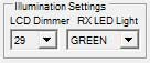
LCD Dimmer
Adjust Alinco's Display Backlight. Use drop down box to select
a value between 01 and 64 where 01 is the dimmest value and
64 the brightest.
RX LED Light [DX-R8 only]
Choose Alinco's RX Lamp colour to be RED or GREEN.
Key/Dial Settings
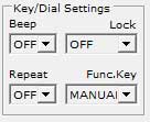
Key Beep
Set Alinco's Key Beep to OFF or ON.
Note! When the program starts if Key Beep is ON then
every command sent by the program to the Alinco results in an annoying Beep.
To avoid this the program will turn off key beep but will leave the
program's screen Key Beep setting showing ON. When the
program shuts down then the key beep will be turned back ON.
If you change the Key Beep setting then the program will honour that
change and not restore the previous setting on program shut down.
Key Lock
Set Alinco's Key Lock to OFF, DIAL or BOTH.
Key Repeat
Set Alinco's Key Repeat to OFF or ON.
Function Key
Set Alinco's Function Key operation to MANUAL or AUTO.
Power Controls
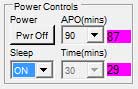
Power Off
This will initiate and immediate Power Off of the attached
Alinco. You will get a confirmation dialogue to confirm the power
off. There program will no longer function until the Alinco is powered
on again and a COM Port connection made.
APO(mins) - (Automatic Power Off)
Selecting any value other than OFF then the Alinco will be
automatically power itself OFF after the set time unless there are Alinco
key actions. Times available to set are 30, 60,
90 and 120 minutes.
Setting a time other than OFF then a flashing nn minutes (with
purple back colour) will be displayed next to the time setting. This
flashing indicator will count down and show you the time in minutes before
the Alinco automatically powers off. Once the time gets to one minute
then the display count will change to -60 seconds (with red back colour) and
count up to 0 seconds when power off will occur and the program will stop
functioning.
Any Alinco key actions (see Note below) will reset the APO timer back to the
value you have selected.
Note! VOL, SQL, IF SHIFT, RIT and Main Tuning Dial operations
will not reset the APO timer.
Sleep [DX-R8 only]
This will turn the Alinco's Sleep Timer OFF and ON.
If ON then then a flashing nn minutes (with purple back
colour) will be displayed next to the time setting. This flashing
indicator will count down and show you the time in minutes before the
Alinco automatically powers off. Once the time gets to one minute
then the display count will change to -60 seconds (with red back colour)
and count up to 0 seconds when power off will occur and the program will
stop functioning.
The time in minutes before the Alinco automatically powers off as set by
the Time(mins) setting.
If ON then the program's Virtual Alinco Display will also show a
"T".
Time(mins) [DX-R8 only]
Sets the Sleep Time. Available times are from 10
minutes to 180 minutes in 10 minute steps.
RF Settings Main and Other Settings

The RF Settings are split into two groups, Main and Other.
This is done for convenience with the Main (mostly likely to be
changed) settings being directly below the main Display. The Other
(less likely to be changed) settings are just to the right of the Main
settings so still ready to hand. A similar layout has been used for
the RF Mode and Step settings.
Most, but not all, of these settings will also be displayed in DriveR8's
Virtual Alinco Display. If displayed then "(displayed)" will be listed
after the available settings values.
Documentation here for these settings is limited to the values
available. Refer to your Alinco's Instruction Manual for full
details.
RF Gain
Values: -20dB, -10dB, 0dB, +10dB (displayed)
AGC Speed
Values: AGC-F (fast) and AGC-S (slow) (displayed)
Narrow Filter
Values: WIDE and NARROW (displayed : Nar = Narrow,
blank = Wide)
Noise Blanker
Values: OFF and ON (displayed: NB = On, blank = Off)
AGC Auto
Values: OFF and ON
SSB Auto
Values: OFF and ON
U/L Tone
Values: OFF and ON (displayed: UT = On (for USB), LT
= On ( for LSB), else other normal RF Mode values)
RF Mode and Step Settings
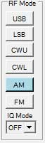
These RF Settings are split into two groups, Mode and Step.
This is done for convenience with the Mode (mostly likely to be
changed) settings being directly to the right of the main Display.
The Step (less likely to be changed) settings are just to the
right of the Mode settings so still ready to hand. A similar
layout has been used for the RF Main and Other settings.
Most, but not all, of these settings will also be displayed in DriveR8's
Virtual Alinco Display. If displayed then "(displayed)" will be listed
after the available settings values.
Documentation here for these settings is limited to the values
available. Refer to your Alinco's Instruction Manual for full
details.
USB - LSB - CWU - CWL - AM - FM/IQ Modes
These buttons set the relevant mode (displayed). The current mode
button with be coloured Blue when set. The FM mode button will change
to an IQ mode button when IQ Mode is set to ON.
IQ Mode
Values: OFF and ON (displayed)
When IQ is set to ON then the above FM button changes to the IQ Mode button.
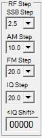
SSB Step
Values: 0.1kHz,0.5kHz,1.0kHz and 2.5kHz
AM Step
Values: 1.0kHz, 2.5kHz, 5kHz, 9kHz and
10kHz
FM Step
Values: 0.5kHz, 1.0kHz, 2.5kHz, 5kHz, 10kHz,
12.5kHz and 20kHz
IQ Step
Values: 2.5kHz, 5kHz, 9kHz, 10kHz, 12.5kHz
and 20kHz
<IQ Shift>
Values: -24kHz to +24kHz in 10Hz steps
To adjust the shift value then Single Mouse Click the IQ Shift display box
and then use the Mouse Wheel, or the Up, Down, Left
or Right Cursor keys.
To reset the shift value to 00000 then Double Mouse Click the IQ Shift
display box.
Virtual Alinco Display

The Virtual Alinco Display is a virtual representation of
the Alinco's digital display. The Alinco has no display data feed so
this virtual display has to be created by DriveR8. Not all information
available on the Alinco's digital display and graphics is available or
represented on DriveR8's virtual display.
This display is a dynamically constructed display based on some
content/status of the Alinco and DriveR8's current control settings.
The display is updated/rebuilt period is as per the Status Pole Time.
The display is also supports the ability to change frequency by use of mouse
wheel in the frequency MHz, kHz and Hz display fields.
The table below shows the relevant supported display items. The two
left columns show the display item numbers as shown in your Alinco's
Instruction Manual.
| DX-R8 Display No. |
DX-SR8/DX-SR9 Display No. |
Alinco Display Item |
DriveR8 Display Item |
| 1 |
1 |
MEMO, MEMO A, MEMO B, Memory Number |
Supported + MEMOX
[DriveR8 special] |
| 2 |
2 |
VFO A and VFO B |
Supported |
| 3 |
5 |
AGC-S and AGC-F |
Supported |
|
3 |
TUNE [DX-SR8/SR9 only] |
Supported |
| 4 |
6 |
RF Gain : RF-20 -10 0 +10 dB Graphics |
Supported as RF-20 -10 0 +10 text |
| n/a |
4 |
SPLIT [DX-SR8/SR9 only] |
Supported |
| 5 |
7 |
* Multifunction Graphic |
Not Supported |
| 6 |
8 |
RF Mode, IQ and Set |
Supported |
| 7 |
9 |
Cursor MHz/kHz Graphic |
Supported |
| 8A |
10A |
Frequency |
Supported + mouse frequency control |
| 8B |
10B |
Memory Name Tag - See 17 |
Supported at bottom of display |
| 9 |
11 |
FUNC function key Graphic |
Not Supported |
| 10 |
12 |
Dial or Key Lock Function Graphic |
Supported as OFF, DIAL, BOTH text |
| 11 |
14 |
NB Noise Blanker |
Supported |
| 12 |
15 |
Nar Narrow / Wide Filter |
Supported |
| 13 |
n/a |
T Sleep Time [DX-R8 only] |
Supported |
| n/a |
16 |
T Tone Encode [DX-SR8/SR9 only] |
Not Supported |
| n/a |
13 |
Transmit Power [DX-SR8/SR9 only] |
Supported |
| 14 |
17 |
BUSY Graphic |
Not Supported |
| 15 |
18 |
S Meter Graphic |
Not Supported - see 17 |
| 16 |
19 |
RIT On/Off and shift |
Supported but no shift +/- frequency |
| n/a |
19 |
TXIT On/Off and shift [DX-SR9/SR9 only] |
Supported but no shift +/- frequency |
| 17A |
10 |
Memory Tag Name |
Supported [DriveR8 special] |
| 17B |
n/a |
Band Display for VFOA & VFOB |
Supported [DriveR8 special] |
Notes for 17A/17B: In place of the S Meter Graphic at the
bottom of the display we instead have an alternative display field for the
following:
- Memory Name Tag - Name tag of current memory channel in use
- Band Information - Band Information - e.g. [LW] 1000 metres - [MW] 375
metres - [HF] 60 metres - [VHF] 9 metres
This means that we have both Frequency and Name (for memory
bank use) and Frequency and Band (for VFoA/VFoB use)
available on the virtual display at the same time.
The frequency Band information is derived as follows:
- If the frequency falls within an Alinco defined range
of band frequencies then the Alinco band name definition is
used.
- If the frequency falls outside an Alinco defined range of band
frequencies then DriveR8 calculates the band metre length to the
nearest 1 metre length
Frequency Display and Control
The frequency display is made of three display fields. nn MHz .
mmm kHz . iii Hz
Each of the display MHz, kHz and Hz fields allows
each of the digits in that part of the frequency to be changed using the
mouse wheel or the up/down/left/right cursor keys.
To change a digit value then left mouse button click on the left edge/side
of the chosen digit and the digit will be highlighted and the mouse cursor
will change from a hand to Up/Down scroll arrows. You can now use the
mouse wheel or cursor keys to change the digit value as long as the mouse
pointer is kept within/over the whole field.
The frequency fields and digits are interlinked thus, for example, 01.999.000
will change to 02.000.000 and back to 01.999.000 with a
mouse wheel forward one click and back one click on the kHz
field. Similarly for the MHz and Hz fields.
This method of frequency changing allows for quick and alternative way of
frequency changing other than via direct keyboard input.
When the Alinco's display is showing a memory name tag the frequency display
will . The memory name tag will however be displayed in the Memory
Control Group's Memory Name Display.
Sleep Time Display [DX-R8 only]
In addition to the associated T indicating that the Sleep Timer
is active, the DriveR8 also shows the time in minutes (with flashing purple
back colour) the time in minutes before the Alinco powers off next to the Sleep
Controls.
Frequency Change Control Group
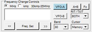
These are the primary VFO frequency controls. Some settings are also
displayed in the Virtual Alinco Display.
VFO-A and VFO-B Buttons
Sets Alinco to use VFO-A or VFO-B. Current setting
results in the button back colour being Blue. (displayed)
VFO A=B Button
Sets Alinco's VFO-A and VFO-B frequency to be the same as
the current frequency.
MHz and kHz Radio Buttons
Sets the Frequency Input Box to be MHz or kHz formats.
Current MHz/kHz setting is saved on program closure and are restored on next
program start.
Band Drop Down
Tunes to frequency as the start of the Band.
Values : 160, 80, 60, 40, 30, 20,
17, 15, 12, 10 metres
RIT Drop Down [DX-R8]
Values: OFF and RIT (displayed)
Actual RIT offset is not displayed.
RIT/TXIT Drop Down [DX-SR8/SR9 only]
Values: OFF, RIT, TXIT, BOTH
(displayed)
Actual RIT and TXIT offset are not displayed.
Note! If TXIT Access is off then only OFF and
RIT are available.
Cursor Drop Down
Sets the Alinco's display Cursor (displayed)
Values: Memory, Band, 1MHz, 100kHz, Step
Frequency Input Box
Here you enter, via the PC keyboard, the frequency to tune to.
See MHz/kHz Radio Buttons. Mouse click this input
box to enable keyboard input.
Input Formats:
- 25 will set 25kHz or 25MHz depending on
MHz/kHz Radio Button settings
- 25. will set 25kHz or 25MHz depending
on MHz/kHz Radio Button settings
- 25.125 will set 25.125kHz or 25.125MHz depending on MHz/kHz Radio
Button settings
Current MHz/kHz setting is saved on program closure and are restored on next
program start.
Frequency Set Button
This will commit / send the frequency value in the Frequency Input Box
to the Alinco.
<< Frequency Step Down Button
Will step change down the frequency value buy the RF Step
value for the current RF Mode active.
>> Frequency Step Up Button
Will step change up the frequency value buy the RF Step
value for the current RF Mode active.
Fc - Frequency Control Panel Button
Will display the Frequency Control Panel.
VFO Scratch Pad
The VFO Scratch Pad is an instant Save and Recall facility.

Whatever Frequency and RF Mode the receiver/transceiver is
tuned to when the "S" Save Button is pressed will result in them
being saved to the Scratch Pad Memory. This memory is a single
location only. When the "R" Recall Button is pressed the Frequency
and RF Mode currently stored in the Scratch Pad Memory will
be recalled and the receiver/transceiver set to that Frequency and RF
Mode. Any data stored in the Scratch Pad Memory will be
displayed on the left of the "S" Save and "R" Recall Buttons.
This program feature allows you to change the Frequency or RF mode away from
your currently tuned values and then instantly restore those settings.
The Scratch Pad Memory data is retained when the program is closed
by writing it to the DrivR8 ini file and restoring the data on program
start.
"S" Save Button
The "S" button will store the currently tuned Frequency and RF Mode
to the Scratch Pad Memory. The currently store frequency and RF mode,
if any, are displayed on the left.
"R" Recall Button
The "R" button will restore the saved Frequency and RF Mode from the
Scratch Pad Memory and the receiver/transceiver tuned to those restored
values. The button is disabled if there is no data stored.
Frequency Control Panel
The Frequency Control Panel with be displayed when the Fc
Button in the Frequency Change Control Group is
pressed.


In many receive only operation usage cases the full DriveR8 Control Panel is
not required are takes up valuable screen space. This is especially
true when using other software to decode transmitted digital modes.
With this smaller control panel you can minimise the main panel and use this
one instead.
Note 1. Frequency and RF Mode changes made with this control panel
are propagated back to the Main Control Panel and Main Display.
Likewise Main Control Panel changes of Frequency and RF Mode will be
propagated to this control panel.
Note 2. The width of the control panel can be increased to the full
PC monitor display width thus improving the resolution of the Frequency
Change Slider.
The position and width of the control panel are saved and will be restored
the next time the panel is used.
Frequency Display
Shows the current frequency tuned to. Format is nn.nnn.nnn (nn
MHz . nnnn kHz . nnn Hz).
RF Mode Change Button
Displays the current RF Mode set. Clicking the button will change the
RF Mode to the next mode in the sequence of USB -> LSB
-> CWU -> CWL -> AM -> FM (IQ)
back to USB.
Note: IQ Mode ON has to be enabled on the Main Control Panel for it
to appear here otherwise it will be FM mode.
Frequency Range Button
Selects the operating range of the Frequency Change Slider. In
the above pictures 4MHz has been selected and lowest settable frequency is
set to 4MHz and the highest settable frequency is set to
5MHz. The current frequency range limits are also displayed at
each end of the slider bar.
Frequency Change Slider
Adjusts the frequency up or down within the selected frequency range
limits. Range width is 1MHz.
The slider supports the following change methods:
- Mouse Click and Drag the slider pointer up (to right) and down (to
left)
- Mouse Click to the LEFT of the slider pointer to step the frequency
down
- Mouse Click to the RIGHT of the slider pointer to step the frequency
up
- Mouse Click and HOLD to the LEFT of the slider pointer to rapid scroll
the frequency down
- Mouse Click and HOLD to the RIGHT of the slider pointer to rapid
scroll the frequency up
- Keyboard Cursor Up/Left keys to step the frequency down (hold to rapid
scroll) (select slider first)
- Keyboard Cursor Down/Right keys to step the frequency up (hold to
rapid scroll) (select slider first)
- Keyboard Page Up key to step the frequency down (hold to rapid scroll)
(select slider first)
- Keyboard Page Down key to step the frequency up (hold to rapid scroll)
(select slider first)
The frequency steps values are the same as those used by the Alinco's rotary
tuning dial for the selected RF Mode:
- USB, LSB, CWU, CWL and modes:
- AM and FM modes: 100Hz
NOTE! Unlike when using the Alinco's rotary tuning dial you
will hear the frequency change.
Scan Control Group

This group of scan controls operate the Alinco's inbuilt scanning
functions. For full details of the Alinco's scan functions please
refer to the Alinco's Instruction Manual.
Note! Special Memory Bank X is excluded and can not be scanned.
If Bank X is active then the Scan Up and Scan Down buttons will be
inoperative.
When any of the scan functions are active then DriveR8's Virtual Alinco
Display will display / emulate the Alinco's display with the exception of
memory name tag. The memory name tag will however be displayed in the
Memory Control Group's Memory Name Display.
Scan Mode Select
Selects Alinco's Scan Modes.
Values: Band, Program, Search and Memory
scans
Scan/Search Width Select
Selects the Alinco's Search scan range/width when in Search scan mode.
Values: 50kHz, 100kHz and 200kHz
Scan Timer Select
Selects the Alinco's time parameters for how long it stops on a frequency
when scanning.
Values: OFF, 0, 1S, 2S, 3S, 5S,
7S, 10S, B0, B1S, B2S ... B10M,
B20M and B30M
Please refer to your Alinco's Instruction Manual for full
details but here is a quick guide:
- OFF - Scans Stops On
Signal - Scan Cancelled - Scan Status is Inactive
- 0
- Scans Stops on Signal - Scan Resumes when signal lost - Scan Status is
Active
- 1S to 10S - Scan Stops on Signal - Scan
Resumes after n Seconds - Scan Status is Active
- B0
- Scan Does Not Stop - Scan Status is Active
- B1 to B30S - Scan Stays on Frequency for n Seconds
before stepping to next - Scan Status is Active
IMPORTANT NOTE! DriveR8 has NO knowledge of the
Alinco's signal BUSY/SQUELCH status. Once DriveR8 Starts or
Stops a Scan then this is what the program takes a fact. The scan
status is either Active or Inactive. However DriveR8 uses an algorithm
of checking if, when scanning, the Alinco is still tuned to the same
frequency. In the case of the Scan Timer OFF value then
DriveR8 will DriveR8 will issue, to itself, a Scan Stop command so DriveR8
will effectively pick up that the Alinco has halted scanning behind
DriveR8's back.
Scan Skip Select
Sets the Alinco's skip action to Alinco's memory location's skip
setting. If a memory location "skip" is set on/checked then if Scan
Skip Select is also set to ON then the Alinco will not stop on that memory
location when scanning.
Values: OFF and ON
Up Scan Button
Starts the Alinco Scanning Up in the selected Scan Mode.
When scanning Up the button will turn colour Green and the Stop Scan button
colour will turn Red.
If the Alinco stops on a frequency then you can either Stop the scan by
hitting the Stop Scan Button or you can resume the scan by hitting the Scan
Up button.
Stop Scan Button
Stops the Alinco Scanning.
If a scan is in progress then the button will be coloured Red.
Down Scan Button
Starts the Alinco Scanning Down in the selected Scan Mode.
When scanning Down the button will turn colour Green and the Stop Scan
button coloured will turn Red.
If the Alinco stops on a frequency then you can either Stop the scan by
hitting the Stop Scan Button or you can resume the scan by hitting the Scan
Down button.
Priority Scan Button
Turns Priority Scan OFF and ON. This is a "toggle"
button.
When Priority Scan is Active the button will be coloured GREEN.
Memory Match Display Group

This is a very unique feature and extremely useful feature, Copyright © Nick
Bailey 2008-2021 and Prior Art - Nick Bailey 2008.
For the above picture the Alinco is tuned to a frequency is
01.005000MHz.
This Display shows how far above, below or exact match the currently tuned
frequency is to a frequency an already defined memory in a Memory Bank
and Memory Location.
The features of each of the separate four elements (one for each memory
bank) are as follows:
- Top left is the frequency stored in the nearest matching memory
location
- Top right is the modulation in the nearest matching memory location
- Left graphic bar displays how far BELOW the current Alinco frequency
is to the nearest matching memory location
- Center box is the nearest matching memory location number (suffix -
None=Main Bank, A=Bank A, B=Bank B, X=Bank X)
- Right graphic bar displays how far ABOVE the current Alinco frequency
is to the nearest matching memory location
- Bottom field is the Memory Name (if set) of the nearest matching
memory location
- NOTE! A perfect frequency match results in both the above and below
graphic bars being full scale deflection
Each of the graphic bars has ten steps. The full scale deflection
range can be set to 0.1kHz, 1kHz or 10kHz in the program's Options
settings. The currently set value is displayed on the top of the
display.
Using the above image as an example you would read the following:
- Graphic bar scale range in 10kHz (current frequency is 01.005000MHz)
- Current frequency is ABOVE Memory Bank Main, Location 35 which has a
defined frequency of 01.000100Mz, and RF mode of AM and a name of
TEST 10
- Current frequency is EQUAL to Memory Bank A, Location 1 which has a
defined frequency of 01.005000MHz, and RF mode of AM and a name of
BIG COW
- Current frequency is BELOW to Memory Bank B, Location 6 which has a
defined frequency of 01.008500MHz, and RF mode of USB and NO name
- Current frequency is ABOVE Memory Bank X, Location 143 which has a
defined frequency of 01.000300Mz, and RF mode of AM and a name of
T1
Using this Memory Match Display, with an appropriate sensitivity, then you
can quickly see, without opening any of the Memory Bank View/Edit functions,
if the frequency you are tuned to is an exact or near match to something you
have already stored/defined in one of the memory banks.
Memory Tune Controls Group

These controls drive the Alinco's Memory Banks Main, A and B.
They also control DriveR8's Special Bank X.
In the above image Memory Bank X is selected and Location 000
tuned to. The memory Name is RADIO DRIVER8.
Memory Input Box
Here you enter, via the PC keyboard, the memory number to tune to.
Mouse click this input box to enable keyboard input.
Valid Inputs:
- Bank Main / Mem / Memo : 0 to 199
- Bank A / Mem A / Memo A : 0 to 201, P1, P2 (where P1=200
and P2=201)
- Bank B / Mem B / Memo B : 0 to 201, P1, P2 (where P1=200
and P2=201)
- Bank X / Mem X / MemX : 0 to 199
Memory Set Button
This will select the memory number in the Memory Input Box in the
current selected memory Bank. (displayed)
Memory Name Display
This display shows the Name of the selected memory location.
Name is RADIO DRIVER8 in the above image.
Memory Bank Main, Bank A, Bank B, Bank X Select
Buttons
The Mem, MemA, MemB and Mem X buttons select the
associated memory bank. The selected bank's button will turn colour
Blue. (displayed)
Memory Bank Main, Bank A, Bank B, Bank X Selected
Memory Displays
These displays, below each Bank button, the memory number location selected
in each bank. (displayed)
<< Memory Down Button
Steps currently tuned memory location down to the next used location.
Empty locations are skipped.
>> Memory Up Button
Steps currently tuned memory location up to the next used location.
Empty locations are skipped.
Memory Protection Drop Down
Values: OFF and ON - (also applies to Special Bank Mem X)
Note! When Memory Protection is ON then the Main Control Panel
STORE button is disabled (pop up message is issued). Also
the Memory Bank View/Edit is restricted to only the Viewing, Fast
Tune, Find, Read All Again and Printing functions. Pop up message is
issued.
Memory VFO Drop Down
Values: OFF and ON - (does NOT apply to Special Bank
Mem X)
ON allows the currently memory tuned frequency to be varied
by the Alinco's Main VFO Tuning Dial. OFF prohibits
memory frequency being changed by VFO on Banks Main, A and B.
Note1: Memory Bank X is unaffected by this setting.
Note2: Change of frequency via the Virtual Alinco Display's frequency
change methods are still possible.
Memory Banks Control Group
This group contains the Memory Banks Bank Main, Bank A, Bank
B, Special Bank X and Store to Bank controls.

Bank Main, Bank A, Bank B and Special Bank X
This gives access to Setting, Viewing and Editing the Alinco's Memory
Banks and DriveR8's Special Memory Bank X.
The Alinco uses MEMO, MEMO A and MEMO B to refer to
it's three memory banks. DriveR8 refers to these as Bank Main,
Bank A and Bank B respectively.
When View/Edit is pressed then a new form is loaded where you have
full control over that memory bank's settings.
Note! With the exception of Special Memory Bank X the editing
of the Alinco's memory MEMO (Bank Main), MEMO A (Bank A) and MEMO B (Bank B)
Edit/Write functions are disruptive in that the Alinco has to be put
into Alinco Memory Write Mode. Once this occurs then when the
Edit/Write has been completed then the Alinco will go into a PASS
state. This PASS state leaves the Alinco in disrupted state in that
the Alinco's front panel controls will no longer function. However the
Alinco can still be controlled from the DriveR8 program.
Note! When Memory Protection is ON then the Main Control Panel STORE
button is disabled (pop up message is issued). Also the Memory
Bank View/Edit is restricted to the Viewing, Fast Tune, Find, Read All Again
and Printing functions. Pop up message is issued.
View/Edit Memory Bank Settings
Each memory bank has it's own form/panel that will open when the View/Edit
button is selected. The form title bar will display Memory Bank
Main, Bank A, Bank B or Bank X as
appropriate.

Unlike other programs that use a tabbed interface to display a range of
memory locations I have chosen to consolidate all the memory locations onto
a single navigable form with a scrollable grid view of the memory data.
The main advantage of doing this is that one can sort the data by column
(by clicking column header). This sort is at this stage is a form
view sort. However you can use the Commit
Sort button to commit this sorted data back to the memory banks.
The vertical height of the form/grid has been chosen so that memory
locations are paged up and down in 25 location chunks at a time.
Form Differences by Memory Bank
The table below shows the differences between the Memory Bank Forms.
Item
|
Bank Main
|
Bank A
|
Bank B
|
Bank X
|
| Locations |
0 - 199 |
0 - 201 |
0 - 201 |
0 - 199 |
| Name |
7 characters |
7 characters |
7 characters |
16 characters |
| P1 and P2 |
NO |
P1=200/P2=201 |
P1=200/P2=201 |
NO |
| Skip |
YES |
YES |
YES |
NO |
| Split Frequency |
YES |
YES |
YES |
NO |
| Read All Again Button |
Enabled |
Enabled |
Enabled |
Disabled |
For Bank A and Bank B the Alinco's Program Memory Locations P1 and
P2 are replaced by 200 and 201 respectively
Form Differences by Receiver vs
Transceiver
Table below shows the differences in column layouts/visibility based on
receiver and transceiver rig ability.
| Receiver |
Mem.No. |
Name |
Frequency |
Mod |
Gain |
AGC |
Filter |
Noise Blanker |
Skip |
Select |
|
|
|
| Transceiver |
Mem.No |
Name |
Frequency |
Mod |
Gain |
AGC |
Filter |
Noise Blanker |
Skip |
TX Power |
Tone |
Split Frequency |
Select |
| Bank X RX |
Mem.No |
Name |
Frequency |
Mod |
Gain |
AGC |
Filter |
Noise Blanker |
Select |
|
|
|
|
| Bank X TX |
Mem.No |
Name |
Frequency |
Mod |
Gain |
AGC |
Filer |
Noise Blanker |
TX Power |
Tone |
Select |
|
|
Clearly TX function columns will not be displayed on receiver only DX-R8
rigs. Similarly DriveR8's Memory Bank X is limited in what it is
able to do.
Grid Columns / Data Fields
The column/field details (left to right) are as below: (all columns/fields
can be sorted by clicking the field/column header)
The following columns/fields are always accessible: (DX-R8 / DX-SR8 /
DX-SR9)
- Row Header Prefix - this is a blank non editable field used to
select a row in the grid. Can be used for Fast Tune.
- Memory - this is a fixed named non editable field showing the
memory location number. Can be used for Fast Tune.
- Name - this is an editable field allowing you to name a
memory. Names up to 7 characters are allowed for Banks Main, A,
and B. 16 characters for Bank X. Can be used for Fast
Tune.
- Frequency - this is an editable field allowing you to enter a
frequency. The format is nn.nnnnnn MHz. Any entered
frequency is check for an Out of Band value. It can be
used for Fast Tune. This input field also supports CB
Channel direct input via associated prefix keys. See Frequency
Prefix Keys.
- Modulation - this is an editable field via a combo box.
Available values are USB, LSB, CWU, CWL,
AM and FM.
- Gain - this is an editable field via a combo box.
Available values are -20dB, -10dB, 0dB and +10dB.
- AGC this is an editable field via a combo box. Available
values are AGC-F (fast) and AGC-S (slow).
- Filter this is an editable field via a combo box.
Available values are WIDE and NARROW.
- Noise Blanker - this is an editable field via a combo
box. Available values are OFF and ON.
- Skip - this is an editable field via a combo box.
Available values are OFF and ON.
- Select - this editable check box is used in conjunction with
the Memory Select and Select Function
buttons.
The following columns/fields are only accessible on transceivers: (DX-SR8
/ DX-SR9)
- TX Power - this is an editable field via a combo box. Available
values are HIGH, LOW and S-LOW.
- Tone (CTCSS) - this is an editable field via a combo box.
Available values are OFF and ON.
- Split Frequency - this is an editable field allowing you to
enter a frequency. The format is nn.nnnnnn MHz. Any
entered frequency is check for an Out of Band value.
Note! Memory Bank X is a special software program bank. This
uses VFOA or VFOB for tuning as selected in the program Options.
Unlike with the rigs memory banks we can not therefore have a defined split
frequency for each of Bank X's memory locations. Instead the rig's
main VFO single split frequency is used.
Frequency Prefix Keys and Suffix Keys
The frequency input field supports several Frequency Prefix Keys and
Suffix. These keys fall into the following categories:
- CB Frequency Quick Input Keys - quick frequency input for known
CB Legal Channels (US / EU / UK)
- CB/Freeband/11M Quick Input Keys - quick frequency input for
known CB/Freeband/11M Channels including Mid/US/EU legal channels
- Others - to be added as appropriate or asked for
Prefix Category
(with country default modulation) |
Prefix
(any case) |
Prefix
Example |
Prefix Action
Frequency |
Prefix Action
Tag Name |
Default
Modulation |
| UK CB Channel Quick Input (legal) |
cbuk |
cbuk10 |
Set 27.69125 MHz |
CBUK10 |
FM |
| EU/CEPT CB Channel Quick Input (legal) |
cbeu |
cbeu19 |
Set 27.18500 MHz |
CBEU19 |
FM |
| US CB Channel Quick Input (legal) |
cbus |
cbus40 |
Set 27.40500 MHz |
CBUS40 |
AM |
| CB/Freeband/11M - Band A - Super Super Low |
fba / sslo |
fba10 / sslo10 |
Set 25.72500 MHz |
BANDA10 / SSLO10 |
USB |
| CB/Freeband/11M - Band B - Super Low |
fbb / slo |
fbb11 / slo11 |
Set 26.18500 MHz |
BANDB11 / SLO11 |
USB |
| CB/Freeband/11M - Band C - Low |
fbc / lo |
fbc12 / lo12 |
Set 26.65500 MHz |
BANDC12 / LO12 |
USB |
| CB/Freeband/11M - Band D - Mid (legal) |
fbd / mid |
fbd13 / mid13 |
Set 27.11500 MHz |
BANDD13 / MID13 |
USB |
| CB/Freeband/11M - Band E - High |
fbe / hi |
fbe14 / hi14 |
Set 27.57500 MHz |
BANDE14 / HI14 |
USB |
| CB/Freeband/11M - Band F - Super High (inc.10M amateur) |
fbf / shi |
fbf15 / shi15 |
Set 28.03500 MHz |
BANDE15 / SHI15 |
USB |
In addition we have modulation suffix keys that changes the default
modulation.
Prefix and Suffix Category
(with non default modulation) |
Prefix
(any case) |
Suffix
(any case) |
Prefix
Example |
Prefix Action
Frequency |
Prefix Action
Tag Name |
Default
Modulation |
| UK CB Channel Quick Input |
cbuk |
a |
cbuk10a |
Set 27.69125 MHz |
CBUK10 |
AM |
| UK CB Channel Quick Input |
cbuk |
f |
cbuk10f |
Set 27.69125 MHz |
CBUK10 |
FM |
| EU/CEPT CB Channel Quick Input |
cbeu |
l |
cbeu19l |
Set 27.18500 MHz |
CBEU19 |
LSB |
| US CB Channel Quick Input |
cbus |
u |
cbus40u |
Set 27.40500 MHz |
CBUS40 |
USB |
| CB/Freeband/11M - Band D - Mid |
fbd / mid |
a |
fbd13a / mid13a |
Set 27.11500 MHz |
BANDD13 / MID13 |
AM |
| CB/Freeband/11M - Band A - Super Low |
fbe / hi |
f |
fbe14f / hi14f |
Set 27.57500 MHz |
BANDE14 / HI14 |
FM |
Fast Tune Control
Pressing the Tune button will cause the Alinco to directly tune to
the frequency and modulation defined in the current row / location
in the grid.
One can also perform a Fast Tune by double left mouse button
clicking any of the cells in the Header Prefix, Location, Name
or Frequency fields.
For Memory Banks Main, A and B then the Alinco will
be tuned to that memory Bank and Location. For Special Bank X then the
tuning is done via the VFOA or VFOB tuning mechanism. The choice of
VFO to be used is set in Options Settings Form.
Find Control
Pressing the Find button will use a simple string search term and/or
a frequency as entered in the Text String box below the
button. This is a simple search looking for the text or frequency you
have entered. There are no advanced "this and than but not the other"
options. The Find command is currently restricted to finding
data in the Name and Frequency fields only.
However all table columns are sortable by clicking the header field so like
data is also readily grouped together, e.g. all Modulations of the same
value.
When entering text into the Text String box any leading and trailing
spaces will be removed but middle spaces will be retained. So
becomes " London " becomes "london" and " London Airport
ATC " will become "london airport atc".
All text searches are case insensitive.
When entering a frequency into the Text String box the entered
frequency should ideally be in MHz format and include the decimal
point. Example "25.620".
When the required data is found the table view focus is taken to that table
cell and the cell background colour is set to light blue to highlight the
found data. This will happen for all subsequent finds. All found
cells in this find/search session will remain back highlighted until the Find
Form is closed. This means that you can change find/search data
within a session and build up a back highlighted composite view.
All highlights are removed on form closure.
The Find button will find and highlight data cell by cell on each
button click.
Store Control
The Store button will ONLY operate to complete the Store
To Bank process initiated on the Main Control Panel
form. This button is enabled and coloured Green when Store To
Bank is pending. The button will not be enabled until a
channel store location has been chosen. To complete the store
process then click a memory location prefix field (whole row
colour will now turn Blue to indicate that the channel row has been
successfully selected) and then click the Store button.
The Store To Bank process can be cancelled by closing the memory bank form
or by pressing the Store Cancel button on the Main Control Panel
form.
Any pending store is cancelled on form closure.
Memory Select Control
The Select All button allows the selection of all memory locations
in the bank. When this button has been selected the button colour will
turn to Green and it's label change to Deselect.
The Select Count Display displays the number of currently selected
channels.
Selecting one or more channels will enable the Select Function Control
buttons.
Function Select Controls
There are eight function command buttons in this group. These commands
will ONLY operate on the memory location(s). When a command
button is available for use the button colour will turn to Green.
- Delete - this will delete all data associated with the selected
memory location(s)
- Save to File - this will save all data associated with the
selected memory location(s) to a file of your choice. A File Save
dialogue will be shown. This save is a PART save and the
file is marked with a "#part#" and when the saved file is
reloaded it will only overwrite the Alinco settings as defined in the
file.
- Format CSV - when checked the Save To File function
will create a CSV file containing Name, Frequency in MHz and Modulation
only. No file headers are added. If you wish to share your
data with others in CSV format then check this option before
pressing. To use / import a CSV file then you have to use the DriveR8Convert
utility program.
- Copy / Move - this will copy all the data associated with the
memory location(s) into a copy buffer. This will then enable to Paste
and Move buttons. The Copy / Move button will then
turn Yellow to indicate that a Copy / Move action is in
progress.
- Paste - this will Paste the data in the copy buffer to
the selected target memory location. To select a target
location simply mouse left button click the header prefix field to
select and highlight the whole row. The data copied will now be pasted
to here when you select the Paste button.
- Move - this will Move the data in the copy buffer to
the selected target memory location. To select a target location
simply mouse left button click the header prefix field to select and
highlight the whole row. The data copied will now be moved
to here when you select the Move button. The source data
will be deleted only after the move has been successful.
- Copy2Bank - this will copy all the data associated with the
memory location(s) into a copy buffer. The Copy2Bank and Paste2Bank
buttons will then turn Yellow to indicate that a Copy2Bank/Past2Bank
action is in progress. You now have to open another Memory Bank
form to complete the process. Move to bank is not supported.
- Paste2Bank - this will Paste the data in the copy
buffer to the selected target memory location. If a Paste2Bank is
pending the on this form then the Copy2Bank button will be coloured
Yellow and the Paste2Bank button coloured Green. To select a
target location simply mouse left button click the header prefix field
to select and highlight the whole row and click the Paste2Bank
button. The data copied will now be copied to here when
you select the Paste2Bank button. Move to bank is
not supported.
Cell Copy and Paste Control
The data grid / table supports SINGLE cell Copy and Paste
to and from the Windows Clipboard. This means that cell data
can be copied and pasted both within DriveR8's Memory View/Edit
form and also outside e.g. to and from a spreadsheet cell or other document.
The supported actions/methods are:
- Select a cell and use the Copy and Paste buttons in
this control group
- Select a cell and use Ctrl-C and Ctrl-V key actions
- Right Mouse Button click to select a cell and use the pop-up Context
Menu options
I will hopefully be revisiting better Copy and Paste support in the future
but it is fraught with issues issues and DriveR8 stability is my
major objective.
Duplicate Frequency Group Control
The Warning On check box when checked will cause a message box to be
displayed if the frequency you have just entered into a channel also exists
in any other channel. Existing channels containing this frequency will
be listed in the message box. The frequency entry is still permitted
but you may wish to review it. The setting of Warning On is
stored in the ini file on program close and is reloaded on program start.
Remember you can bring all the same frequencies together for review by
sorting the frequency data column (by clicking column header).
Read All Again Control
The Read Bank button will initiate a full read of all the
Alinco's memory data for current Memory Bank. This button is
not enabled for Special Memory Bank X. A full all
again is only required if you have manually changed or stored memory data
on the Alinco whilst DriveR8 is running and supposed to be in control.
Commit Sort Control
The Commit Sort button will commit/store back to the memory banks
and the receiver/transceiver the data as you have sorted on the memory
display form. By having a separate Commit Button one can
sort and play with the data as viewed on the memory bank form as you
please without making any real changes until you hit the Commit Button.
Memory Print Controls
The Memory nnn - yyy buttons will raise a printer dialogue where you
can select the required printer and printer properties to print the chosen
memory location data. The chosen selection are printed 25 to a page.
The ALL Mems button will cause all memory bank locations of data to
be printed. This will produce 4 pages of 25 channels per page.
Store To Bank Control
The Store To Bank button is only enabled when the Bank Main,
Bank A, Bank B and Special Bank X are NOT
open.
When the button is pressed the following things happen:
- The current frequency and modulation are stored to a temporary buffer
- If the current frequency and modulation are already stored then a Duplicate
Store Dialogue is displayed showing the duplicate Memory Location
in each of the Banks. You can "OK" to continue or "Cancel"
- The button turns Green to indicator that there is now a Store
action pending
- The button text turns to Cancel
- Now select a target Bank to View/Edit for you to
complete the store process
- A Store Information Message box is displayed for 5 seconds
confirming the frequency and modulation to be stored
You can now complete the Store as described here.
To Cancel a pending store then just press the button again.
DX-SR8 and DX-SR9 Transmitter Controls
The controls in this group are only visible when a DX-SR8 or DX-SR9
Transceiver is connected. Currently the CW controls relating to
Electric Keyer, Paddle, Side-Tone and Break In functions are not supported
but if requested I will add support for them but you will have to help me by
undertaking your own testing for me.
Please refer to the Alinco's Instruction Manual for any additional
information not covered here.

TXMit Button
Mouse clicking the TXMit button will put the Transceiver into
transmit mode and the button colour will turn RED. In addition the
Virtual Alinco Display modulation Mode background colour will turn RED.
On mouse button release the Transceiver will return to Reception
mode.
The above transmission mode colour RED indications will also occur when
the MIC/microphone PTT (Push To Talk) button is depressed.
Spilt Frequency Set
This button will allow the setting of a Split Frequency for the currently
selected VFO. An input form is opened.

The button also displays the currently set Spilt Frequency value.
If the button background is Grey then the Spilt Frequency mode is set to
OFF. If the button background is Green then the Spilt Frequency mode
is set to ON.
When a Memory Bank MAIN, MEMA or MEMB and Location are in operation then
the button will display the set Split Frequency for that memory bank and
location.
If using Memory Bank MEMX then the Spilt Frequency displayed will be that
of the VFO being used.
PTT Lock
The PTT Lock can be set to ON or OFF. When ON
the TXMit and PTT buttons are locked out from use.
TX Power
This allows the setting of the transmitter power. It can be
set to S-LOW, LOW and <>HIGH. The approximate
powers used for each power level depend on modulation mode and are defined
in the table below.
| Settings |
HIGH |
LOW |
S-LOW |
| SSB / CW / FM |
100 Watts |
10 Watts |
1 Watt |
| AM |
40 Watts |
4 Watts |
0.4 Watts |
Speech Compressor
The Speech Compressor can be set to ON or OFF.
When ON the speech compressor increases the talk power.
Split
Split Frequency Operation can be set to ON or OFF.
When ON split frequency operation is enabled and a different
frequency is used for Transmit and Receive modes. Split operation and
setup is complex so please refer to your Alinco's Instruction Manual
for additional information and usage.
CTCSS
The CTCSS Tone Operation can be set to ON or OFF.
When ON then the CTCSS frequency tone used is as set in the CTCSS
Tone setting.
CTCSS Tone
Selects the required CTCSS Tone frequency.
TXIT Access
TXIT Access can be set to ON or OFF. When set
to OFF the TXIT function is not allow to be set/used.
To set TXIT then see RIT/TXIT control.
Antenna Tune
When the Antenna Tune button is clicked then any attached Alinco
EDX-2 or other compatible antenna tuner is activated.
The button colour will turn RED. In addition the Virtual Alinco
Display TUNE background colour will turn RED.
Note! As there is no signaling from the Transceiver to tell
DriveR8 that the antenna tuning is complete DriveR8 uses a fixed indication
time of 5 seconds. This I'm told is a typical average time for the
antenna tuning process to complete. The definitive status of the
tuning process will be indicated on the Transceiver's actual display.
Status Latency Display Group

This display shows two values:
1. On the left - Status Latency
Time being the actual average time in milliseconds during any given
1 second period the program takes to do the following:
- Get all required status data from Alinco
- Build and display the Virtual Alinco Display
2. On the right - the currently set Status
Pole Time in milliseconds
Below the time displays is information on the current Virtual
Display/Status Refresh Period method and the current COM port data read
method.
These can be:
- Auto Interval (RL) - status interval is program calculated and
READLINE is used for data reading
- Auto Interval (RE) - status interval is program calculated and
READEVENT is used for data reading
- User Interval (RL) - status interval is User set and READLINE is used
for data reading
- User Interval (RE) - status interval is User set and READEVENT is used
for data reading
READLINE is the program's default COM port data read method and for use
will Alinco's / other makes of USB to Serial Interface Adaptors. For
user wishing to use traditional genuine serial port communication then
READEVENT should be set in the 'DriveR8-ini.ini' file.
See Virtual Display/Status Refresh Period Options setting
for more details.
Clock Display Group

The Clock Display shows the current Local and GMT/UTC date and
time. These are taken from your PC's Time Zone and Date and Time
Settings.
The current Local or GMT/UTC setting as set in the Options menu is shown
with a green coloured background.
It is not possible to adjust these times with the DriveR8 Program.
Notepad and Auto Save Group
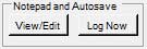
The program has built in Notepad and Autosave functions.
When the View/Edit button is pressed a new Notepad
Log and Auto Saved Frequencies form is opened. Also if the
keyboard [CTRL] is pressed at the same time then the Frequency Log File is opened.
When the Log Current is button pressed then the current frequency
and reception mode of the Alinco, along with the date and time are added to
the Notepad Log. Depending on the settings on the Notepad
Log and Auto Saved Frequencies form a number of actions may take
place.
Notepad Log and Auto Saved Frequencies

This form is split into two main components. A Notepad Group
on the left and an Auto Saved Frequencies Group on the right.
The Date and Time entries will be in either GMT (06/02/2017,13:48:55,GMT)
or Local time (06/02/2017,13:48:55,LCL). The logging of is in
GMT/UTC or Local as determined by the Options setting Program
Time Settings in GMT/UTC check box.
Both groups have Goto Top and Goto Bottom buttons which will
scroll the relevant data views to the top and bottom of their respective
data views. No further detailed explanation required.
If either the Notepad Auto Log function and/or the Auto Saved
Frequencies function are enabled then frequency data will be
stored/added to the file called "DriveR8-frequency.log"
Notepad Log Group
This Notepad information is stored in a file called "DriveR8-notepad.txt"
and this will be located in the program directory or where you have chosen
to locate your other Alinco data files. It is capable of storing 2048
MB of data. The data will be loaded and saved when the program starts
and ends. The current Notepad usage in Bytes/KB/MB is displayed at the
top of the Notepad area. You will receive a program warning when the
currently stored data in the file exceeds 5 MB. When you start to
receive these warnings then you should ideally backup your data as soon as
possible and then use the Clear Notepad function.
Loading and saving data exceeding 5 MB will slow down the program start and
shutdown performance.
The entries in the Notepad are in CSV format.
To manually make a new Notepad entry then double click in the notepad text
area and a new data and time stamped, frequency and modulation entry will be
created. To this entry, or any other entry you can add your own text.
Auto Log Checkbox
This check box, when checked, will enable the Notepad Auto Log
function. When the Alinco is scanning and hits and stops on active
frequency then the current date, time, frequency,
and modulation are automatically entered into the Notepad area
together with an AE (auto entry) additional tag.
Clear Notepad Button
This will clear the current Notepad of all data. Please
ensure you have backed up/copied this data as appropriate. You will
be given a confirmation dialogue and option to cancel the clear request.
Freq Log View Button
This will open the Frequency
Log File. The Frequency Log File can also be opened via the
main control panel form Notepad and Autosave View/Edit
Button.
Auto Saved Frequencies Group
Auto Saved consists of 200 separate storage locations where "hits"
can be automatically saved. This information is stored only in the
program's DriveR8-ini.ini file. Any of your personal Alinco
saved data files will not contain these autosave frequencies.
Auto Saved Quick Tune and Store
Any stored entries can be "Quick Tuned" by mouse double clicking any
particular entry. The Alinco will be tuned to the relevant frequency
and modulation. Should you wish to Store this frequency to a
particular Memory Bank and Number then use Store Button
and complete the store process.
Auto Save Checkbox
This check box, when checked, will enable the Auto Save Frequency
function. When scanning and the Alinco hits and stops on active
frequency then the current date, time, frequency, modulation,
and Hit Count are automatically entered into the next available Auto
Saved location. In addition an AS (auto saved)
additional tag is added to the reciprocal entry the Notepad
area. This AS entry will be supplemented with either a NEW=nnn
or and OLD=mmm entry. These entries show if the frequency and
modulation mode are NEW and have been stored in location new nnn
or they are OLD and were previously stored in an old mmm
location.
Once the Auto Saved data/locations reach 200 then the entries will wrap back
to location 1 thus overwriting previous data. It is your
responsibility to manage these special 200 locations/data.
Clear Auto Saved Button
This will clear the current Auto Saved locations of all
data. Please ensure you have Stored any entries you wish to
keep in a Memory Bank/Location. You will be given a confirmation
dialogue and option to cancel the clear request.
Frequency Log File and View Form
If either the Notepad Auto Log function and/or the Auto Save
Frequencies function are enabled then frequency data will be
stored/added to the file called "DriveR8-frequency.log". This
log is cumulative and can be user edited or deleted.
Frequency Log File View Form

The Frequency Log File View Form allows the Frequency Log File to be
viewed.
This is opened either by the View Freq Log button on the Notepad
Log and Autosaved Frequencies form or by pressing the keyboard [CTRL]
button and clicking the Notepad and Autosave Group's View/Edit
button on the main control panel.
The log file is opened as a snap shot ready only view. Any additional
updates to the file will not be loaded unless the form is Refreshed
or the form is closed and re-opened again.
Refresh Button
This will reload the whole frequency log file again thus picking up any
additional updates made since the form was first opened.
Auto Refresh Combo Box
The Auto Refresh allows the form to self refresh at defined intervals.
The available intervals are: 0, 5, 10, 30, 60, 120, 180 and 240
seconds. (see notes below)
NOTES!
- An interval setting of 0 turns Auto Refresh OFF and is
the default value when the form is opened.
- Auto Refresh can only be enabled if the size of the frequency
log file is less then 2 Megabytes. This restriction is
done for performance issues associated with the continual reloading of a
large log file. A 2MB file will still contain over 24,000
entries/hits.
- Manual Refresh will always reload the log file of any size.
Frequency Log File Details
If either the Notepad Auto Log function and/or the Auto Save
Frequencies functions are enabled then frequency data will be
stored/added to the file called "DriveR8-frequency.log". This
log is cumulative and can be user edited or deleted .
The log file is a simple CSV file with entries as follows:
11/04/2020,14:25:41,GMT,00.518000, FM,003,[MAIN],040,0000000
11/04/2020,14:25:59,GMT,27.841250, FM,001,[MEMA],025,CBUK25
11/04/2020,14:29:25,GMT,05.250000, AM,002,[MAIN],125,TEST
TRANSMIT
11/04/2020,14:30:48,GMT,01.100000,USB,001,[MEMB],010,BINGO00
11/04/2020,14:43:51,GMT,27.781250,
FM,001,[MAIN],019,CBUK19
11/04/2020,14:44:26,GMT,27.601250,
FM,001,[MAIN],000,CBUK01
11/04/2020,14:45:12,GMT,27.601250,CWU,001,[MAIN],001,CBUK01
11/04/2020,14:57:18,GMT,27.781250,
FM,002,[MAIN],019,CBUK19
11/04/2020,14:57:59,GMT,27.791250, FM,001,[MAIN],020,CBUK20
11/04/2020,15:21:36,GMT,27.791250, FM,004,[VFOA],---,
11/04/2020,16:55:41,GMT,07.095950,LSB,002,[VFOB],---,
12/04/2020,15:14:50,GMT,07.031880,LSB,001,[VFOB],---,
12/04/2020,15:15:08,GMT,27.791250, FM,003,[VFOA],---,
12/04/2020,16:52:00,GMT,27.781250,
FM,003,[MEMX],019,CBUK19
The fields are date,time, local (LCL) or GMT,
frequency, modulation and hit count (000-999), Tuning
Control, Memory Number, Memory Name.
The Tuning Control is the source of the frequency entry.
This will be one of VFOA, VFOB, or Memory Banks MAIN,
MEMA, MEMB or MEMX.
The hit count is a count of the times the given frequency has been
encountered.
If the count = 0 then this a frequency that has been logged when the Auto
Saved Frequencies function is NOT enabled.
If the count is 1 or greater then the frequency was logged when the Auto
Saved Frequencies function was enabled.
As the log is cumulative all logged frequencies encountered may or may not
appear in the current Auto Saved Frequencies table depending on when
the table was last cleared or the storage locations wrapped.
Apart from writing data to this file the program does nothing else with the
data. The data is intended for use by anyone interested in analysing
the gathered data.
Alinco Read Refresh
DriveR8 is designed to be the Master in controlling the
Alinco. Manual intervention on the Alinco will, in most cases, cause
the program's view of the Alinco to become out of step with the Alinco's
altered state. This Read Refresh function will cause DriveR8 to
refresh it's view of the Alinco.
See Running when Connected to a Powered On Alinco for
more detailed information and when to use this Read Refresh function.
ReceiverFTP.html File (HTML Frequency Monitor File)
DriveR8 can optionally create an HTML Frequency Monitor
File called ReceiverFTP.html which resides in DriveR8's program
directory.
This HTML file contains information regarding the Current Frequency being
monitored an optionally the previously monitored frequency information.
See Options for the controls available for this file.
The primary purpose of this file is to allow DriveR8 to document, in HTML
format, information regarding the currently monitored and previously
monitored frequencies. This is so that people who feed/broadcast their
receiver's audio output via audio streaming programs, such as Zello, can
also provide a web page which tells their listeners what they are currently
listening to.
I have also written a small AutoFTP utility that can be used to monitor this or
any other file and FTP the file when it changes to a location of the user's
choice.
Audio Record and Player Group
The Audio Record and Player Group contains the controls and options
for the program's ability to record and playback recorded sound.
Before detailing the various controls and options a little further
information is required about the basic sound implementation used by this
program. There are also options to change the recording input source,
file naming convention and quality of the recording in "Recording
Source, File Name Header and Quality".

PLEASE NOTE! It may be illegal to record certain
types of, or even *any*, radio transmission/traffic in your particular
Country, State or Jurisdiction. It is your responsibility to
check the legality of recording any transmission. Whilst
there may be no restriction on recording, the playing of or sharing
that recording with another person(s) or party(s) may be illegal.
The author does not condone, support or otherwise encourage any
illegal activity. This program's recording features must ONLY
be used in compliance with the laws of your particular
Country, State or Jurisdiction.
Sound System Overview
It was never intended that the sound recording and playback functions of
this program would be able to compete with other sound recording and
playback software available. Instead the design focuses on using the
existing resources that will/should already be available on your Windows
system and tightly coupling these to the program thus allowing for a more
closely controlled Alinco recording environment and recording control
options.
It is important to understand the following points:
- No sound feed is available over the Alinco USB connection so you will
have to plug into one of the Alinco's audio outputs to obtain a sound
feed.
- To record the program uses your default sound card and input feeds on
your system. You need to set these up in your sound card controls
along with the recording volume level. Recording input always
defaults to the default sound input as set in Windows. However you
can change the input source in the Options panel "Recording
Source, File Name Header and Quality".
- When setting recording volume level remember that you can also make
adjustments with the Alinco's volume level as well.
- To playback recorded sound files the program uses your default media
player for .WAV files.
- All recoding is to WAV files only. Remember to set the
appropriate "quality" in the Options panel "Recording
Source, File Name Header and Quality". As the Alinco's audio
signals are of low/medium quality it is recommended to set a lower
quality level to reduce recorded file sizes.
- All sound is recorded to a continuously written WAV file. This
enables the current/last recording (even during recording) to be be
immediately replayed without having to open a specific WAV file.
- All recorded WAV files are automatically saved in the "wav" sub
directory of the program's installation directory. Unlike
with the Alinco settings/data files it is not possible to specify a
target location for recorded files.
- There is the option to record the WAV files to Sub Directories. See WAV Record to Sub Directories.
- All recorded file names are determined by the program and take the
form either "frequency-modulation-yymmdd-hhmmss-timezone.wav" or
memory "name-bank-number-yymmdd-hhmmss-timezone.wav".
Details on how to select which form is to be used and more details on
the name formats can be found in "Recording File Name
Header and Quality".
- I thought long and hard about the file naming convention and this is
the only one that captures the details of the recording and also allows
sorting by frequency and date and time ordering.
Record/Play Controls
These consist of four buttons. Record, Play, Pause
and Stop. Just to the right of these are two information
lines.
The top/first line displays the current status, this being Stopped
(in black) or Recording, Recording Paused and the
recording input source and sample rate (in red), e.g. Recording LINE Input
@ 11025.
The second/bottom line displays nothing/blank if status is Stopped.
If recording then the root name of the file for the recording is
displayed. Depending on the Options settings then this is either the
frequency and modulation, e.g. 01.172100-AM.wav or the memory tag
name-bank-location, e.g. SOUTH_N-MEMA-012.wav (in red).
All buttons start with neutral colours. Only the Record
and Play buttons are initially enabled.
Please read the functions of these buttons taking into consideration the Automatic
Record/Settings/Options which can override/take control of the
buttons.
Record Button
The Record button when pressed will turn Red and become disabled,
recording of the current audio sound stream will start. The Pause
button will turn Yellow and become enabled. The Stop
button will turn Grey and become enabled. The recording can be paused
or stopped. Please Note! the current recording will have
a file name starting with the initial frequency or memory data the
Alinco was tuned to when the recording first started.
Pause Button
The Pause button will become enabled and turn Yellow when the Record
button is pressed. If pressed the current recording or playback
will be paused and the button text will change to Resume. Subsequent Pause
button presses will toggle the Pause/Resume action.
Play Button
The Play is always enabled. The Play button when
pressed will play back the currently recording or the last recorded sound
using your system's default sound/media player.
Stop Button
The Stop button when pressed will stop the current sound
recording. All buttons will revert to their neutral
colours. The Record and Play buttons will remain
enabled.
Play Saved Button
This button is specifically for accessing and playing files that have been
previously recorded and saved to the wav directory. When
clicked a file open dialogue box will open where you can choose a WAV file
to playback. This playback function uses your default play program for
WAV files and the playback will open in that program's own separate window
and it's controls will then take over. This Play Saved
function is totally independent from the above Record, Play, Pause and Stop
functions and thus you can be actively recording Alinco audio whilst also
listening to previously recorded files.
COM Port Control Group
The COM Port Control Group is for managing the communications port
to which the Alinco is connected. It consists of the following
components:
- Current Port and Speed Display
- Port Selection Box (not normally required)
- Refresh Ports Button (not normally required)

Note! Currently the program only supports and lists port names named COMn
or COMnn, e.g. COM7 or COM13.
The DriveR8 Control Program and the Alinco use 9600 baud, 8 data bits, no
parity and 1 stop bit. The DriveR8 Program will try to configure any
selected port to these settings. If you experience communication
problems then it is suggested to try setting these values in Windows
- Control Panel - Device Manager - Ports - Port Settings for the
relevant port.
When the DriveR8 program starts it enumerates all available COM ports and
adds them to the list of available port. It will also scan these
ports looking for your powered on Alinco. If there are no COM
ports available or the program fails to detect your Alinco an error message
will be displayed and the program will enter No Alinco Connected
mode. You will then need to:
- Click the port Refresh Button and if required manually
select the correct COM port
- Close and Restart the program
The program does not support dynamic port detection in that ports or
devices added or removed whilst the program is operating are not
automatically added or removed from the list of available ports. The
program does however have a port Refresh button that performs this
function and will then attempt to connect to the Alinco.
COM Port Display
The COM Port Display shows the currently selected Communications
Serial Port and Port Speed.
It also shows the status of communication as seen by the DriveR8
Program. The background light colour indicates the following status:
- RED - There is no selected and valid COM port available on the
system or an error occurred on that port
- GREEN - A valid COM port on the system has been selected and is
operational
COM Port List Box (use not normally required)
When the program starts it will detect all the COMn and COMnn ports
currently available on your PC. It will also search these ports
looking for your Alinco. If your Alinco is not powered on or the
program fails to find it then you will have to manually select the COM port
yourself.
The COM Port List Box contains a drop down list of all communication
ports that are named COMn or COMnn and are available on your PC. If
your Alinco is not powered on or the program fails to find it then you will
have to manually select the COM port yourself. You should select the
appropriate port for your interface.
If you are unsure of which port to use then do the following:
- Ensure your interface is connected to the PC
- Open Windows - Control Panel - Device Manager - Ports
and review the list of ports and most importantly check the names of
devices against each listed port
- Note device names and use the port named USB Serial Port (COMn)
COM Refresh Button (use not normally required)
This R button when click will cause the program to go through a port
detection routine that will remove missing or invalid ports from the
available port list and add any new ports found.
COM Error Retry Counts
The program supports the following COM error retry strategy.
- Command Cycle Retry - should either of the Send or Receive command
cylces fail then the program will flush all COM input and output buffers
and then repeat the Send/Receive cycle THREE times.
If the program is unable to successfully recover then the program will
display permanent COM error messages.
No Alinco Connected Mode
The program is designed to run when connected to an Alinco via the Alinco's
USB connection. The program will enter and run in No Alinco
Connected mode whenever there are no COM ports available on the system
or a port has not been selected or an Alinco is not detected.
When running in No Alinco Connected mode the Title Bar on the form
will also contained the text "No Alinco Connected!" Only
program specific controls will be enabled.

The program will automatically exit No Alinco Connected mode
as soon as a valid COM port has been selected and an Alinco is present.
Support, Program Suggestions, Recommendations and Bug
Reports
I welcome any suggestions, recommendations or bug reports. These
should be sent to:
| DriveR8 |
@ |
nick-bailey |
. |
co |
. |
uk |
I can not guarantee to fix or implement what you report/suggest but what I
can say is that this DriveR8 Program would not be what it is today without
the feedback, suggestions and bug reports that I have received.
Warranty, Liability and License Agreements
The DriveR8 Control Program is hereunto referred to as the 'Program'.
In using the Program you are agreeing to accept all of the terms and
conditions stated herein.
The Program is currently Freeware (see http://en.wikipedia.org/wiki/Freeware) with a
Careware/Charity status and objective (see http://en.wikipedia.org/wiki/Careware). It
operates with no limitations.
The author reserves the right to change the program status and limitations
on any future release. Existing releases will retain their status and
your right to use them but support may not be available.
The Program is supplied 'ASIS' and the author neither accepts,
implies nor offers any warranty, liability or any other responsibility for
any damages, loss or other claim of any type in respect of this Program, its
usage or consequence of its usage.
**You use it at your own risk**.
The Program has no guarantee of support or implied right to support.
The Program is the sole Copyright of the author and all rights are
reserved. The author's Copyright is restricted to those files
containing 'DriveR8' in their name and any other file clearly written by the
author. The Copyright includes the intended operation, design and
function of the Program. The Program requires other runtime
files to function and the Copyright of these files belongs to their
respective owners/authors.
The creator of this Program asserts that the appearance of the user
interface screens is/are a work of art and therefore attracts Copyright
protection under EU law.
You may not disassemble, reverse engineer or otherwise interfere with any of
the Program executable files.
You may not use this Program for any illegal or unlawful purpose.
You may not sell, rent or otherwise charge for this Program.
The preferred availability and distribution of the Program is from the
authors website to which you and others should refer to.
You may however freely distribute the Program but must do so entirely free
of charge, save for any reasonable charge in respect of any physical media
used in its distribution. All electronic or other non physical media
distribution must be free of all charges. You may not alter, modify,
remove, or in any way change any of the files that comprise the DriveR8
Program Control Package as released by the author. You may add your
own text or other information files but these must be clearly identifiable
as yours, added by you and in such a manner that they do not in any way form
part of the DriveR8 Control Program or could easily be considered to be part
of the DriveR8 Control Program. Neither must they infringe the
Copyrights of any author, person or organisation and must not contain
offensive, illegal or other illicit material.
Should you believe that your version of the Program package has been subject
to any infringement of the above conditions then please contact the author
immediately providing as much information as possible.
Prior to release, the author has to his satisfaction checked that the
Program is free of any Virus or other potentially destructive software/code,
but this is not guaranteed.
Before using the Program you are advised to Virus check the version of the
Program you have prior to using it. The author's Website may also
carry MD5 checksums for the critical files. You are advised to verify
these as well.
You are requested to fully read this and any other documentation prior to
installing and using the Program. In using the Program you are
agreeing to accept all of the terms and conditions stated herein.
The author hopes that you find DriveR8 Control Program both easy to use,
reliable and of assistance to you and your Alinco. He may be contacted
at his Email address and would certainly like to hear of any bugs,
criticism, suggestions etc. that you may have.
Please remember. The Program is supplied 'ASIS' and you use it at
your own risk.
Recognised Trademarks, Proprietary Code and Copyrights
Visual Basic, Windows, Windows XP/Vista/7/8/8.1/10, .NET are
registered trademarks of the Microsoft Corporation.
Alinco is a registered trademark of Alinco Incorporated.
This product contains:
- Alinco proprietary and/or copyright control codes. © Alinco ,
Inc - All rights reserved. Used with permission.
- Un4Seen BASS Library functions. © un4seen developments - All
rights reserved. Used under license.
- radio24 BASS.NET Library functions. © radio42, Germany - All
rights reserved. Used under license.
Other Trademarks may be mentioned in this document and the author
acknowledges them.
© Nick Bailey 2016-2023