
| IF150 Project Build |
|---|
| Home Page IF150
Commands |
|---|
| Part Description |
Maker's Part Number |
Project / Circuit Reference |
Usage |
| Arduino Uno (R3) |
A000066 |
Arduino Uno (R3) Module |
Required |
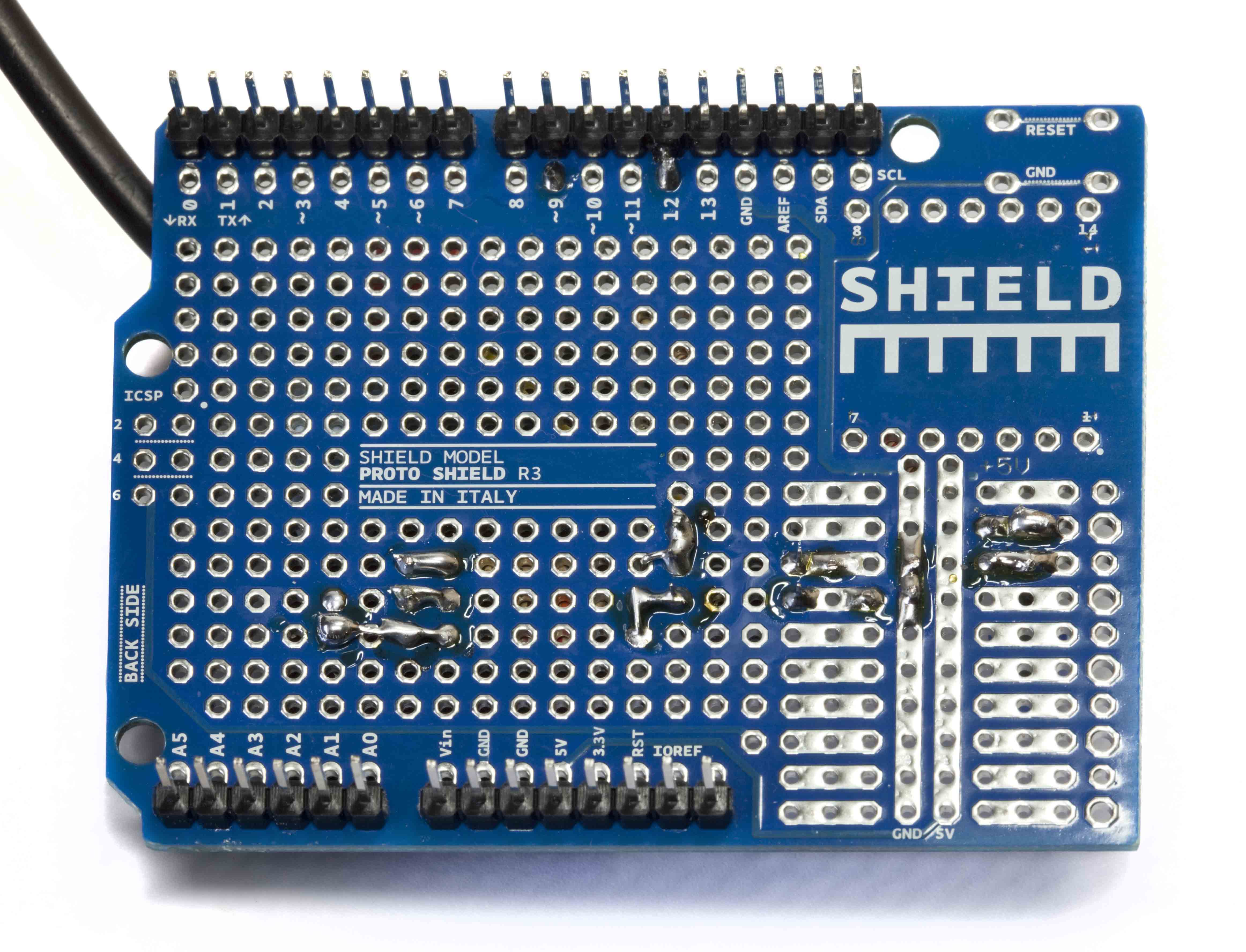
| Arduino Proto Shield Rev3 PCB only | A000082 |
Opto-isolation & Level Shifting Board |
Optional |
| Arduino Case |
A000009 |
Arduino Case |
Optional |
| USB 2.0 A to B Cable |
any USB 2.0 A-B cable |
PC to Interface Cable |
Required |
| 3.5mm jack plug |
any |
Interface to HF-150 cable |
Required |
| 500mm of single core screened cable |
any |
Interface to HF-150 cable |
Required |
| Opto-Isolator - 4 Pin DIL |
SFH618A-2 |
OPT1 |
Required |
| Transistor, NPN, 45Vceo, 100mA, hfe
250,TO92 ** see note below |
BC550C |
Q1 |
Required |
| Resistor 1K, 0.25W, metal or carbon film | any |
R1 |
Required |
| Resistor 1K, 0.25W, metal or carbon film | any |
R2 |
Required |
| Resistor 10K, 0.25W, metal or carbon film | any |
R3 |
Required |
| Resistor 150R, 0.25W, metal or carbon film | any |
R4 |
Required |
| Resistor 1K, 0.25W, metal or carbon film | any |
R5 (for optional status LED) |
Optional |
| LED, 5mm, single colour, T-13/4 package |
any |
LED1 (optional status LED) |
Optional |
| Sleeving for LED leads to create 10mm standoffs |
any |
led standoff support |
Optional |
| Pin Strip - 0.1 inch pitch - 36 way |
any |
for connecting boards together |
Required |
| Small cable ties |
any |
for securing cable / strain relief |
Required |
| Pretty IF150 Label to your own design |
any |
Optional |
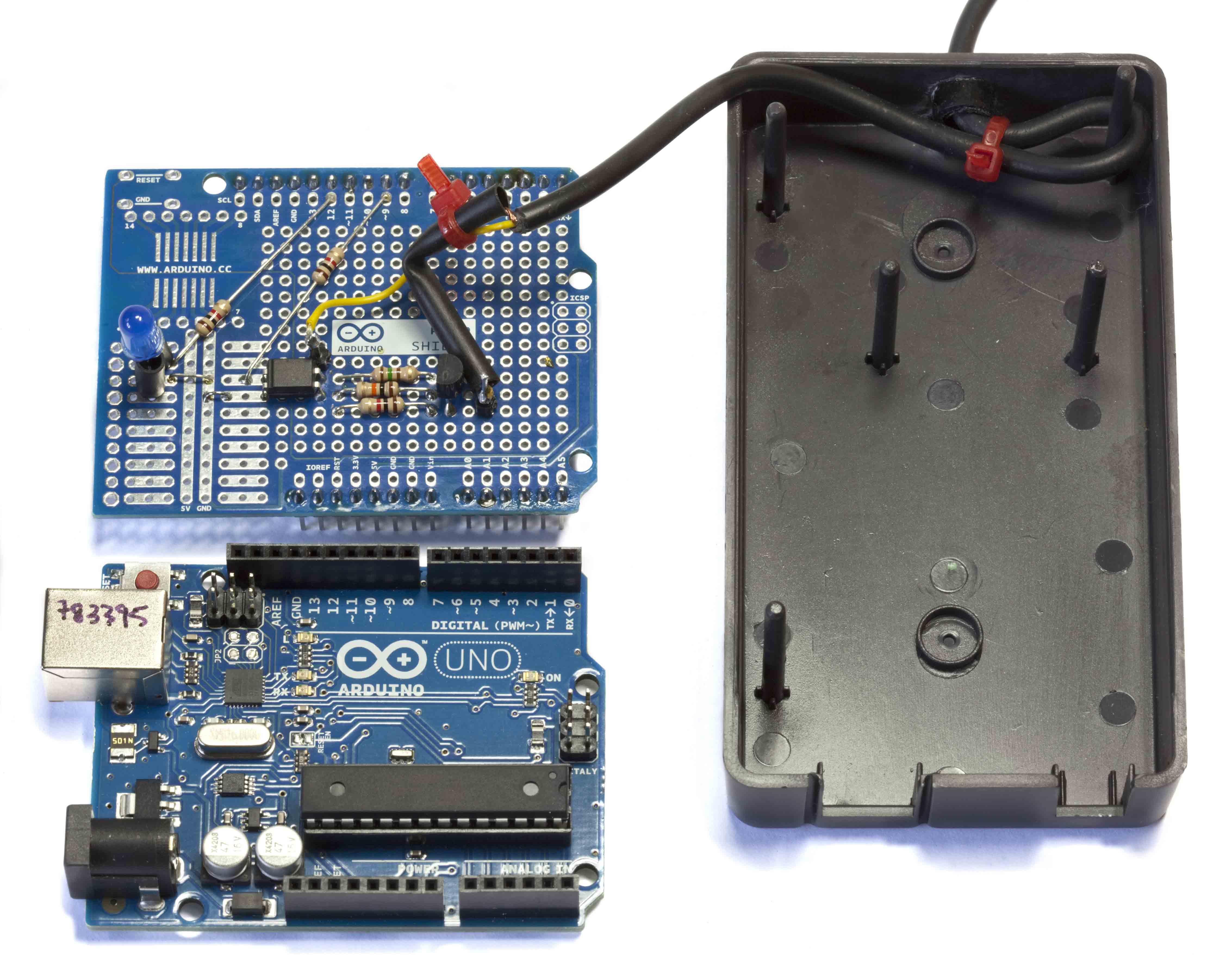
This board / circuit has to make connection with the Arduino Uno Board on Pins 9, 12 and GND (ground). My suggested design is the "piggy back" Proto Shield layout. You may wish to have flying leads connecting the boards in your own packaging but you must connect to Pins 9, 12 and GND on the Arduino Uno.
My suggested design "piggy back" layout allows for the Status LED (LED1) to be mounted on 10mm standoffs and is specifically located to allow the Led to protrude through a custom drilled hole in the Arduino Case upper half.


You should see response text similar toEnter ident
IF150 Control Interface (C) N. R. Bailey 2012
Version V1.0.5P 04 Jul 2012
You should see response text similar toThese two commands will confirm that the Arduino board is responding correctly to commands.
IF150-V1.0.5P-S.99999999-NRB-A.99999999
The receiver should change mode to USBEnter mod am
The receiver should change mode to AMEnter frq 1000
The receiver should tune to 1000 kHAs you enter each command you will see that the Status LED will illuminate while the command is being processed. If the LED remains illuminated then this means that the command you entered was not recognised/supported. Try entering boo. The LED should remain illuminated until the next command is successfully processed. So if you enter help or ? then LED should turn out after the command is processed.
| Home Page Site
Index About Me
Privacy Contact Us Marmotta
PhotoArt |
|---|